​
Showing posts with label with. Show all posts

Saturday, August 31, 2013

Controlling A Relay With A Digital Logic Level Circuit

Description 
The schematic below illustrates 4 methods of controlling a relay with a digital logic signal. Figure (A) can probably be used in most cases where the relay coil requires 100 mA or less and the input current is 2 milliamps or more. The resistor value (R) is determined from the input voltage and the available current. For example, a 5 volt input signal supplying 2 milliamps would require (5-.7)/.002 = 2150 ohms, or a 2.2K standard value. If the transistor has a minimum current gain of 50, there will be 100 mA of current available for the relay coil. The following table shows various resistor values that can be used to obtain various relay coil currents assuming a transistor current gain of 50 such as the 2N3053. 74XX refers to standard TTL logic, 74LSXX refers to low power TTL logic, 74HC is high speed CMOS and CD40XX is the older CMOS devices. The currents given are approximate values and may not be correct for all devices but should be close. 
Input Voltage - Input Current - Relay coil current - Standard Resistor

  • 4 - 74LSXX .0004 - 20 milliamps - 8.2K
  • 4 - 74XX .0008 - 40 milliamps - 4.3K
  • 4 - 74SXX .001 - 50 milliamps - 3.3K
  • 5 - 74HCXX .004 - 200 milliamps - 1K
  • 6 - 74HCXX .004 - 200 milliamps - 1.3K
  • 5 - CD40XX .0003 - 15 milliamps - 13K
  • 12 - CD40XX .0006 - 30 milliamps - 18K
Figure B can be used when the input voltage is the same as the relay coil voltage. The voltage on the emitter of the transistor will be about 0.7 volts less than the input, so a 12 volt relay would operate on 11.3 which should be close enough. No resistor is needed since the emitter follower configuration presents a high impedance at the input. The input current will be the relay coil current divided by the transistor gain. For example a 120 ohm relay coil will draw 100 mA at 12 volts and if the transistor gain is 50, the input current will be about 2 milliamps.
Figure C can be used to provide additional gain when the input current is very small. You can also use a Darlington transistor in place of the two transistors which is a better approach, but this idea works just as well when you dont have a Darlington transistor handy. The overall gain will be the product of the individual gains of the two transistors or about 2500 for two transistor with a gain of 50 each. This will enable supplying over 250 mA to the relay with only 100 microamps of input current. The R value will depend on the input voltage and current and gain of the first transistor. For example, using a 5 volt input and 100 microamp current and transistor gain of 50, the R value will be 5 minus two diode drops (5 - 1.4) divided by the input current times 50, or about (5 - 1.4) / (.0001 * 50) = about 750 ohms. So this setup can be used when controlling heavy duty relays with low power CMOS logic signals.
Figure D can be used to reverse the relay action so that it engages when the input is low and disengages when the input is high. The R value is determined the same as in Figure A. The R1 value should be high enough to ensure saturation of the first stage and low enough to saturate the second stage. For example, if a 12 volt relay coil requires 100 mA and the driving transistor gain is 50, then the base current will be 100/50= 2 mA and the R1 value must be less than 6000 ohms so that 2 mA does not drop more than the supply voltage of 12. If the first transistor gain is 50 and the input current is 100 microamps, the collector current will be 5 mA and the R1 value must be greater than 2400 ohms so that 5 mA drops the entire supply voltage of 12. So we need to select something between these two limits of 2.4K to 6K, something around 4.3K would be near the midrange.
Circuit Diagram
{ Read More }


Friday, July 12, 2013

Subwoofer Filter and Low Pass Filter with LM741

The acoustics of converting a filter, there are many aspects of the economic viability of the more famous are baxandal filter low and high frequency filters and crossover Acoustic space is transformed into sub-domains, so that the Thursday Speakers. Applications, we offer a filter, the limits of the region to transform acoustic (20-20000Hz) in the region of 20-100Hz.

Subwoofer Filter and Low Pass Filter Circuit Diagram


The signal for a first high pass filter C1, C2, P1, which is undesirable level DC input. A lowpass filter consisting of R3, R4, C3 prevents frequencies above 10 kHz, which do not benefit from this design, and it would be that the instability and noise. The summary amp invert signal.

The low Summary of the amplifier signals go to a second low-pass filter to prevent the frequency from the speakers. I decided, a second order, as this box with a closed place feature. If you have a circuit with a valve system, and then simply close the Wind (Roll a pair of socks and pick at the port / Wind), this will give you a sealed box instead.
{ Read More }


Wednesday, July 10, 2013

DC to AC Inverter with IC CD4047

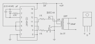
This DC to AC inverter circuit work based on unstable multi vibrator does. In this circuit, IC CD4047 is chosen as a heart of unstable multivibrator, because this IC type gives a complementary output that has opposite phase to another ( pin 10 and 11 as seen in Figure 1), and has 50 % duty cycle that satisfy to generate a pulse for inverter.

DC to AC Inverter with IC CD4047 Circuit Diagram

DC to AC Inverter Circuit Diagram

{ Read More }


Tuesday, July 9, 2013

Battery Switch With Low Dropout Regulator

In the form of the LT1579 Linear Technology (www.linear-tech.com) has produced a practical battery switch with an integrated low-dropout regulator. In contrast to previous devices no diodes are required. The circuit is available in a 3.3 V version (LT1579CS8-3.3) and in a 5 V version (LT1579CS8-5), both in SO8 SMD packages. There is also an adjustable version and versions in an SO16 package which offer a greater range of control and drive signals. The main battery, whose terminal voltage must be at least 0.4 V higher than the desired output voltage, is connected to pin IN1. The backup battery is connected to pin IN2. The regulated output OUT can deliver a current of up to 300 mA. The LDO regulator part of the IC includes a pass transistor for the main input voltage IN1 and another for the backup battery on IN2.

Battery_Switch_With_LDO_Regulator_Circuit_Diagramw

The IC will switch over to the backup battery when it detects that the pass transistor for the main voltage input is in danger of no longer being able to maintain the required output voltage. The device then smoothly switches over to the backup battery. The open-drain status output BACKUP goes low to indicate when this has occurred. When neither battery is able to maintain the output voltage at the desired level the open-drain output DROPOUT goes low. The LT1579 can operate with input voltages of up to +20 V from the batteries. The regulator output OUT is short-circuit proof. The shutdown input switches off the output; if this feature is not required, the input can simply be left open.
 
 
Streampowers
{ Read More }


12V Powered 12V Lead Acid Battery Charger with Indicator

Some of you might wonder why a charger is needed at all, to charge a 12 Volt battery from a 12 Volt source! Well, firstly the "12 Volt" source will typically vary anywhere from 11 Volt to 15 Volt, and then a battery needs a controlled charge current and voltage, which cannot result from connecting it directly to a voltage source. The charger described here is intended for charging small 12 Volt lead acid batteries, such as the gelled or AGM batteries of capacities between about 2 and 10 Ah, using a cars electrical system as power source, regardless of whether the car engine is running or not. I built this charger many years ago, I think I was still in school back then. On request of a reader of my web site, Im publishing it now, despite being a rather crude circuit.

12V Powered 12V Lead Acid Battery Charger with Indicator
It works, it is uncritical to build, and uses only easy-to-find parts, so it has something in its favor. The downside is mainly the low efficiency: This charger wastes about as much power as it puts into the battery. The charger consists of two stages: The first is a capacitive voltage doubler, which uses a 555 timer IC driving a pair of transistors connected as emitter followers, which in turn drive the voltage doubler proper. The doubler has power resistors built in, which limit the charging current. The second stage is a voltage regulator, using a 7815 regulator IC. Its output is applied to the battery via a diode, which prevents reverse current and also lowers the voltage a bit.

12V Powered 12V Lead Acid Battery Charger with Indicator
The resulting charge voltage is about 14.4V, which is fine for charging a gelled or AGM battery to full charge, but is too high as a trickle charger, so dont leave this charger permanently connected to a battery. If you would like to do just that, then add a second diode in series with D3! There is a LED connected as a charge indicator. It will light when the charge current is higher than about 150mA. The maximum charge current will be roughly 400mA. There is an auxiliary output, that provides about 20V at no load (depending on input voltage), and comes down as the load increases. I included this for charging 12V, 4Ah NiCd packs, which require just a limited current but not a limited voltage for charging.

12V Powered 12V Lead Acid Battery Charger with Indicator
Note that if the charge output is short-circuited, the overcurrent protection of U2 will kick in, but the current is still high enough to damage the diodes, if it lasts. So, dont short the output! If instead you short the auxiliary output, the fuse should blow. I built this charger into a little homemade aluminum sheet enclosure, using dead-bug construction style. Not very tidy, but it works. Note the long leads on the power resistors. They are necessary, because with shorter leads the resistors will unsolder themselves, as they get pretty hot! The transistors and the regulator IC are bolted to the case, which serves as heat sink. The transistors dont heat up very much, but the IC does.


Source by Streampowers
{ Read More }


Monday, July 8, 2013

Designing A Li Ion Battery Charger with Load Sharing MCP73837


Batteries often serve as the main energy source for portable electronic devices. Although they depend on batteries, portable consumer electronic products, such as GPS devices and multi-media players, often consume energy directly from an ac-dc wall adapter or accessory power adapter (or “Auto Adapter”) when the battery is low or the device is in a stationary mode. Due to their cost effectiveness over their useful life, rechargeable batteries are often used for the power source of the portable electronic device.

Attributes such as “relatively high energy density” and “maintenance free” make Lithium-Ion (Li-Ion) batteries popular in the portable consumer electronic products. Refer to the application note, AN1088, “Selecting the Right Battery System For cost Sensitive Portable Applications While maintaining Excellent Quality” (DS01088) for characteristics of Li-Ion batteries. Some examples of how to properly design with Li-Ion batteries will be discussed in this application note. [Link] 
{ Read More }


Sunday, July 7, 2013

5 Band Graphic Equaliser circuit with LA3600 and PCB

General Description
Graphic equalisers are a must in any good hi-fi systems! They enable you to shape the response of the system to the particular room, or in recordings to improve deficiencies of the equipment or the original recording. A good equalizer, used with skill can dramatically improve the quality of your listening pleasure.
This equalizer has five bands which cover all the audible frequencies, centred at 100, 320, 1,000, 3,500 and 10,000 Hz. The spacing between peak frequencies is two octaves which is quite adequate for most domestic applications. Frequency adjustment is 12dB/octave.
 
The circuit is for one channel and if you want to use it for STEREO you should build two, one for each channel of your system.
Technical Specifications – Characteristics
Working voltage: 6-15V DC
Frequency response: 20Hz-20KHz
Current: 60 ma
How it Works
This equaliser has five bands which cover all the audio frequencies, around 100, 320, 1,000, 3,500 and 10,000 Hz.
The circuit is for one channel and if you want to use it for STEREO you need two. The circuit consists of one LA3600 IC.
The circuit has been designed so that when the potentiometers are in the middle of their travel the signal is not affected at all. Turning a potentiometer in either direction will affect the corresponding frequency range accordingly. The maximum output voltage without distortion is 1 Vpp. The equaliser operates from a 12 VDC power supply which makes it suitable for use in home or car.
Construction
This work is not very difficult and if you stick to a few rules you should have no problems. The soldering iron that you use must be light and its power should not exceed the 25 Watts. The tip should be fine and must be kept clean at all times. For this purpose come very handy specially made sponges that are kept wet and from time to time you can wipe the hot tip on them to remove all the residues that tend to accumulate on it. The construction of the equaliser is very easy if you follow the diagrams and our advice carefully. The only really sensitive component are the IC. Start building the circuit by soldering the pins and the IC sockets in their places on the p.c. board. Solder then the resistors, the capacitors, making sure that the electrolytic are inserted the right way round before soldering them, and finally the potentiometers.
 
 Depending on the size and the shape of the case you are going to use for the project you can either solder the potentiometers on the p.c. board directly or use short pieces of shielded audio cable to connect them with the rest of the circuit. When you have finished soldering the components on the board check everything for possible mistakes, clean the board with a solvent to remove all traces of soldering flux and insert the IC’s in their sockets. Make sure that you align them properly and that you do not bend their pins during insertion. Make then the following connections using shielded cable for the input and output and preferably twisted twin cable for the power supply.
- The supply (6-15 VDC recommend 12volt DC) must be connected at points 1 (+) and 2 (-) of the board.
- The input is at points 5 (signal) and 4 (earth).
- The output is at points 3 (signal) and 4 (earth).
If you turn the power on, and the potentiometers of the equaliser are in their middle position there shouldn’t be any notice able difference to the music if the equaliser is inserted or not in the signal path. However turning the potentiometers should produce a noticeable effect to the reproduction.


Parts
C1 = 2.2mF 22v
C2 = 47nF
C3 = 680nF
C4 = 15nF
C5 = 220nF
C6 = 4.7nF
C7 = 68nF
C8 = 1.2nF
C9 = 22nF
C10 = 470pF
C11 = 6.8nF
C12 = 1nF
C13 = 2.2mF
C14 = 100mF 22v
C15 = 100mF 22v
R1 = 4.7k
R2 = 10k
R3, 4, 5, 6, 7 = 100k Potentiometers
IC = LA3600 link
 
{ Read More }


Saturday, July 6, 2013

Build an op amp with three Discrete Transistors

You can use three discrete transistors to build an operational amplifier with an open-loop gain greater than 1 million (Figure 1). You bias the output at approximately one-half the supply voltage using the combined voltage drops across zener diode D1, the emitter-base voltage of input transistor Q1, and the 1V drop across 1-MΩ feed-back resistor R2.
Build an op amp with three discrete transistors circuit diagram
Figure 1. This ac-coupled inverting op amp has an open-loop gain of 1 million. R1 and R2 set a closed-loop gain of −10.

Resistor R3 and capacitor C1 form a compensation network that prevents the circuit from oscillating. The values in the figure still provide a good square-wave response. The ratio of R2 to R1 determines the inverting gain, which is −10 in this example.

You can configure this op amp as an active filter or as an oscillator. It drives a load of 1 kΩ. The square-wave response is good at 10 kHz, and the output reduces by 3 dB at 50 kHz. Set the 50-Hz low-frequency response with the values of the input and the output capacitors. You can raise the high-frequency response by using faster transistors and doing careful layout. Link
{ Read More }


10 10 W Stereo Amplifier with tda2004

Hello! in this post I will show a small amplifier using integrated circuit TDA2004 get two outputs 10 watts, the circuit is very simple, if you want to change the circuit, or a mono version refer to the datasheet tda2004!
The circuit is powered by source between 12 and 15 volts with a current of 1.5 Amperes.
 
See the figure below:
10 +10 W Stereo Amplifier with tda2004

{ Read More }


Solid State Relays Circuit with TIL111

Solid state relays are almost everywhere these days, but they are very expensive. So, your efforts to build their own salary. Especially since it’s only a few parts and circuit simple and straightforward. Solid state relay is not really at all relays. There are no “relay” is available only with electronics, connection works. It works well as a relay, you can use low voltage higher and better. “Relay” between 115/220V AC wires in place, although it was customary, the neutral conductor and leave unchanged phases and neutral.

As long as no voltage (left in picture), the phototransistor TIL111 blocks of energy, and thus is not available. To ensure that the base TIL111 is fed to the transmitter (s) through the 1M resistor. This method prevents the base of transistor BC547B will be low and remains biased ‘on’. Collector is low and the gate (g) TIC106M thyristor, which is still in the country, “off”. 4-diode bridge rectifier circuit has no power apart from a small base and collector current BC547B, which is not enough to turn over the 330-ohm resistor TIC226M triac. Current “Load”, is very small.

Solid State Relays Circuit Diagram

With an input voltage, say 5 volts, the diode in the TIL111 lights up and activates the phototransistor. The voltage drop 1MEG ohm resistor in series with 22K resistance increases demand, which block the BC547B transistor. Collector current of the fact that the AC voltage falls below a certain value, which is VA. This ensures a sufficiently large voltage drop across the resistor 330 ohms triac switches ‘on’. The voltage on triac is currently only a few volts, so that practically the whole 115/220 AC voltage on the “Upload”.

The triac is a 100nF capacitor and impedance of 47 ohms, 100nF capacitor for the 330 ohm resistor is to protect the triac to be undesirable distortions caused by small peaks. To create the possibility of this circuit with different voltages to be switched, added BF256A FET. The FET acts as a current source from the source (s) with a gate (g). This means that this FET determines the current TIL111, regardless of the input voltage (up to a certain tolerance, of course). 1N4148 diode is to protect the circuit from reverse polarity.
(Tony: TIL111 is a so-called “optical coupling” with NPN output and can be replaced with NTE3042)

Good point line, as is the separation of AC and DC voltage, so this circuit is used in many applications, about 1.5 kW, when the triac is mounted on the large size of the cooling fins. “M” appears Triac means it’s 600volt type, “D” for 400V. So be sure to go to the M-type. NTE replacement for this circuit are 600volt types which are more than sufficient for our 110/115VAC. Even if you decide to print for this circuit is enough space between the lines AC and non AC these tracks to be close.
{ Read More }


Wednesday, June 12, 2013

The Pursuit of Superior Taste With Th Cool Car Electronic Accessories

BMW Car - Base iPad

Buying a iPad is a very simple for vehicle owners, but where to put the iPad is a problem. Recently, the luxury brand BMW has released the base of ipad in the car first, it can combine seamlessly with Apples products, including text messages, memos, E-mail and so on.
BMW said that in 2011 all its new products, these will be the standard base with the sale, BMW will be the first comprehensive introduction of Apples automotive OEM manufacturers.
Rolls-Royce portfolio picnic tableware
With the car, the radius of human activity is expanding, and weekend outdoor activities Hupenghuanyou is many peoples regular operations. So, if you have an appropriate combination of picnic utensils, driving some to be the most wonderful time. Recently, Rolls-Royce for the Phantom (quotations picture parameters
Number) with introduction of a special combination of select --- 4 picnic. This set of 4 aluminum alloy used in combination with a picnic, wood, leather and other materials, containers are also sterling silver, crystal and other material, there is no published price, but can be worth the price of a domestic car is for certain. It is reported that
A limited edition of 100 sets of cutlery set will be issued.

Ferrari - H4D Camera
Travel driving, how the line without a camera? Ferrari also buy a camera or tighten their belts it. Recently, Ferrari Hasselblad camera company co Sweden introduced a very luxurious product --- the red Ferrari H4D digital camera. The aircraft is equipped with a
Support 80mm lens and a 50 million pixel digital back, with the Ferrari factory rossofuoco body paint, the most seductive eyes and ears have to be rocket logo, highlighting the elegant look. Current aircraft specifications and price were not disclosed, is said to direct inquiries to the Ferrari, not
Price certainly had a lot of money, the world is only limited sale 499 units.

Lamborghini - Super Performance "Notebook"
With moving car, and the car owner move ultimately the office at any time, it is necessary to have a super-performance notebook for yourself. Recently, as son of the Lamborghini car company founder Ferruccio Lamborghini, Tonino Lamborghini push out of a latest Lamborghini Slim Notebook. This notebook is equipped with Intel Ultra Low Voltage processor, and it is up to 500GB hard drive configuration with wireless LAN and Bluetooth, 13.4-inch LED screen with a resolution of 1366 × 768, Windows7 system pre-installed, configured 4-cell lithium-ion battery. At the same time with VGA, HDMI, USB, headset microphone, multi-card reader and other interfaces to meet the daily needs, the weight of 1.3 kg.
{ Read More }


Latest Sound Effects Generator 8 different sound effects circuit schematic with explanation

Sound Effects Generator (8 different sound effects) circuit diagram

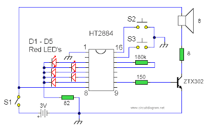
All sounds in this circuit are generated by HT2884. There are 8 different sound effect can be produced that are 2 lazer guns, 1 dual tone horn sound, 2 bomb sounds, 2 machine gun sounds and a rifle shot sound.

Note:
Power is a 3 Volt battery, but the IC will work with any voltage between 2.5 and 5 Volts. Switch S1 is the on / off switch. The output at pin 10 is amplified and drives a small 8 ohm loudspeaker. Pressing S3 once will generate all the sounds, one after another. S2 can be used to produce a single sound effect, next depression gives the next sound effect. Standby current is about 1 uA at 3 Volt, so battery life is very economical.

{ Read More }


Saturday, April 13, 2013

Simple Light Sensor Alarm circuit with NE555

This circuit despatched out an alarm when its LDR sensor is uncovered to mild with the aid of solar or lamp. A 555 astable multivibrator was once used here which despatched sign a tone of about 1kHz upon detecting mild.The sensor when exposed by gentle fulls the circuit and makes the 555 oscillate at about 1kHz with transistor to power current.

The sensor can be shown within the circuit diagram. It has to positioned making an angle of about 30 – 45 stages to the bottom.

Sensitivity will also be modify with P1.  This makes the solar gentle to float thru it to the bottom and stops the alarm from happening as a outcome of the saved mild on the sensor.


{ Read More }


IconIconIconFollow Me on Pinterest