Showing posts with label band. Show all posts

Friday, September 27, 2013

Five band graphic equalizer


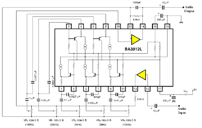
This is a five band graphic equalizer circuit. Comparatively this is a very simple diagram and working voltage is 8 volts. However you can supply up to 15 volts, but we do not recommend that much of supply. The specialty of this circuit is it operates by eighteen pins of a single chip IC ( BA 3812L ). The other components are very less.

The five frequency bands are 100Hz , 300Hz, 1kHz, 3kHz, 10kHz . You can use this simple equalizer with Hi Fi amplification systems as it provide low noise, wide dynamic range and very low distortion. If you want you can use two ICs of BA 3812L and make 10 band graphic equalizer.


{ Read More }


Sunday, July 7, 2013

5 Band Graphic Equaliser circuit with LA3600 and PCB

General Description
Graphic equalisers are a must in any good hi-fi systems! They enable you to shape the response of the system to the particular room, or in recordings to improve deficiencies of the equipment or the original recording. A good equalizer, used with skill can dramatically improve the quality of your listening pleasure.
This equalizer has five bands which cover all the audible frequencies, centred at 100, 320, 1,000, 3,500 and 10,000 Hz. The spacing between peak frequencies is two octaves which is quite adequate for most domestic applications. Frequency adjustment is 12dB/octave.
 
The circuit is for one channel and if you want to use it for STEREO you should build two, one for each channel of your system.
Technical Specifications – Characteristics
Working voltage: 6-15V DC
Frequency response: 20Hz-20KHz
Current: 60 ma
How it Works
This equaliser has five bands which cover all the audio frequencies, around 100, 320, 1,000, 3,500 and 10,000 Hz.
The circuit is for one channel and if you want to use it for STEREO you need two. The circuit consists of one LA3600 IC.
The circuit has been designed so that when the potentiometers are in the middle of their travel the signal is not affected at all. Turning a potentiometer in either direction will affect the corresponding frequency range accordingly. The maximum output voltage without distortion is 1 Vpp. The equaliser operates from a 12 VDC power supply which makes it suitable for use in home or car.
Construction
This work is not very difficult and if you stick to a few rules you should have no problems. The soldering iron that you use must be light and its power should not exceed the 25 Watts. The tip should be fine and must be kept clean at all times. For this purpose come very handy specially made sponges that are kept wet and from time to time you can wipe the hot tip on them to remove all the residues that tend to accumulate on it. The construction of the equaliser is very easy if you follow the diagrams and our advice carefully. The only really sensitive component are the IC. Start building the circuit by soldering the pins and the IC sockets in their places on the p.c. board. Solder then the resistors, the capacitors, making sure that the electrolytic are inserted the right way round before soldering them, and finally the potentiometers.
 
 Depending on the size and the shape of the case you are going to use for the project you can either solder the potentiometers on the p.c. board directly or use short pieces of shielded audio cable to connect them with the rest of the circuit. When you have finished soldering the components on the board check everything for possible mistakes, clean the board with a solvent to remove all traces of soldering flux and insert the IC’s in their sockets. Make sure that you align them properly and that you do not bend their pins during insertion. Make then the following connections using shielded cable for the input and output and preferably twisted twin cable for the power supply.
- The supply (6-15 VDC recommend 12volt DC) must be connected at points 1 (+) and 2 (-) of the board.
- The input is at points 5 (signal) and 4 (earth).
- The output is at points 3 (signal) and 4 (earth).
If you turn the power on, and the potentiometers of the equaliser are in their middle position there shouldn’t be any notice able difference to the music if the equaliser is inserted or not in the signal path. However turning the potentiometers should produce a noticeable effect to the reproduction.


Parts
C1 = 2.2mF 22v
C2 = 47nF
C3 = 680nF
C4 = 15nF
C5 = 220nF
C6 = 4.7nF
C7 = 68nF
C8 = 1.2nF
C9 = 22nF
C10 = 470pF
C11 = 6.8nF
C12 = 1nF
C13 = 2.2mF
C14 = 100mF 22v
C15 = 100mF 22v
R1 = 4.7k
R2 = 10k
R3, 4, 5, 6, 7 = 100k Potentiometers
IC = LA3600 link
 
{ Read More }


Friday, May 17, 2013

AM Transmitter Double Side Band

AM Transmitter  Double Side BandAM Transmitter Double Side Band
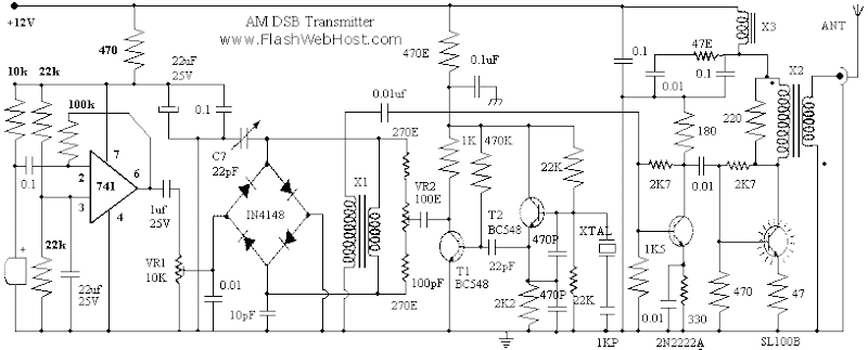
The ambit of AM transmitter is advised to address (amplitude modulated) DSB (double ancillary band) signals. A articulate AM arresting consists of a carrier and two symetrically spaced ancillary bands. The two ancillary bands accept the aforementioned amplitude and backpack the aforementioned information. In fact, the carrier itself coveys or carries no information. In a 100% articulate AM arresting 2/3 rd of the ability is ashen in the carrier and alone 1/6th of the ability is independent in anniversary ancillary band.

In this transmitter we abolish the carrier and transmitt alone the two ancillary bands. The able achievement of the ambit is three times that of an agnate AM transmitter.

Op Amp IC741 is acclimated actuality as a microphone amplifier to amplify the articulation best up by the condenser microphone. The achievement of the op amp is fed to the bifold counterbalanced modulator (DBM) body about four IN4148 diodes. The accentuation akin can be adapted with the advice of preset VR1.

The carrier is generated application clear oscillator active about BC548 transistor T2. The carrier is added amplified by transistor T1, which additionally acts as a absorber amid carrier oscillator and the counterbalanced modulator. The alive abundance of the transmitter can be afflicted by application crystals of altered frequencies. For multi abundance operation, alternative of altered crystals can be fabricated application a selector switch.

Ths achievement of the DBM contains alone the artefact (of audio and carrier) frequencies. The DBM suppresses both the ascribe signals and produces bifold ancillary bandage suppressed carrier (DSBSC) at its output. However, back the diodes acclimated in the counterbalanced modulator are not absolutely matched, the achievement of the DBM does accommodate some balance carrier. This is accepted as carrier leakage. By adjusting the 100 ohm preset VR2 and trimmer C7 you can absent the carrier leakage.

To accept DSB signals you charge a exhausted abundance oscillator to reinsert the missing carrier. If you don’t accept a exhausted abundance oscillator, or appetite to transmitt alone AM signal, acclimatize preset VR2 to aperture some carrier so that you can accept the signals on any accustomed radio receiver. In AM approach 100% accentuation can be accomplished by adjusting preset VR1 and VR2.

X1 – 8+8 Turns Bifalar 24 SWG On TV Balune Core
X2 – Primary 12 Turns, Secondary 4 Turns. 24 SWG on TV Balun Core (dot indicates start of coil).
X3 – 20 Turns 24 SWG on TV Balun Core

Range of the circuit depends on the type of antenna used. It is very important to use matched antenna to radiate the signals effectively. I used horizontal dipole antenna, which is simple and easy to construct. For 7 MHz, ie 40 meter ham band the length of dipole antenna will be 20 meter. Use 75 Ohms co-axial cable to connect antenna and transmitter. I was able to get 57 report from station 80 kilometer away. You can easily add a Linear RF amplifier using IRF830 to get more power.

{ Read More }


Sunday, April 7, 2013

Simple 5 Band Equalizer

This circuit uses a single chip, IC BA3812L to make 5 band graphic equalizer in audio hi-fi system. BA3812L IC is a 5-point graphic equalizer that has all functions integrated on a single IC. This IC is composed of five tone control circuit and input and output buffer amplifier. BA3812L have low distortion, low noise, and wide dynamic range, and is ideal for a variety aperanti Hi-Fi stereo. He also has a wide operating voltage range (3.5V to 16V), meaning he could be adapted for use on most stereo equipment.
5 band equalizer

The five center frequencies are independently set using external capacitors, and therefore act as an output stage buffer amplifier and tone control section is a series of its own, it is possible to do fine control over the frequency bandwidth. By using two BA3812Ls, you can create a 10-point graphic equalizer. Great header and pieces can be set by external components.

The recommended power supply of 8V, but this circuit can work well for supply voltage 9V. Limit the maximum voltage is 16V.

The circuit is given in the diagram operates in around 5 frequency bands:
100Hz , 300Hz , 1kHz , 3kHz , 10kHz
{ Read More }


IconIconIconFollow Me on Pinterest