This is a compact three transistor, regenerative receiver with fixed feedback. It is similar in principle to the ZN414 radio IC which is now no longer available. The design is simple and sensitivity and selectivity of the receiver are good.
AM Receiver Schematic

Notes:
All general purpose transistors should work in this circuit, I used three BC109C transistors in my prototype.The tuned circuit is designed for medium wave. I used a ferrite rod and tuning capacitor from an old radio which tuned from approximately 550 - 1600kHz. Q1 and Q2 form a compund transistor pair featuring high gain and very high input impedance. This is necessary so as not to unduly load the tank circuit.
The 120k resistor provides regenerative feedback,between Q2 output and the tank circuit input and its value affects the overall performance of the whole circuit. Too much feedback and the circuit will become unstable producing a "howling sound". Insufficient feedback and the receiver becomes "deaf". If the circuit oscillates,then R1s value may be decreased; try 68k. If there is a lack of sensitivity, then try increasing R1 to around 150k. R1 could also be replaced by a fixed resisor say 33k and a preset resistor of 100k. This will give adjustment of sensitivity and selectivity of the receiver.
Transistor Q3 has a dual purpose; it performs demodulation of the RF carrier whilst at the same time, amplifying the audio signal. Audio level varies on the strength of the received station but I had typically 10-40 mV. This will directly drive high impedance headphones or can be fed into a suitable amplifier.
Construction:
All connections should be short, a veroboard or tagstrip layout are suitable. The tuning capacitor has fixed and moving plates. The moving plates should be connected to the "cold" end of the tank circuit, this is the base of Q1, and the fixed plates to the "hot end" of the coil, the juction of R1 and C1. If connections on the capacitor are reversed, then moving your hand near the capacitor will cause unwanted stability and oscillation.
Finally here are some voltagee checks from my breadboard prototype.This should help in determining a working circuit:
All measurements made with a fresh 9volt battery and three BC109C transistors with respect to the battery negative terminal.
Q1 (b) 1.31V
Q2 (b) 0.71V
Q2 (c) 1.34V
Q3 (b) 0.62V
Q3 (c) 3.87V
AM Receiver Schematic
All general purpose transistors should work in this circuit, I used three BC109C transistors in my prototype.The tuned circuit is designed for medium wave. I used a ferrite rod and tuning capacitor from an old radio which tuned from approximately 550 - 1600kHz. Q1 and Q2 form a compund transistor pair featuring high gain and very high input impedance. This is necessary so as not to unduly load the tank circuit.
The 120k resistor provides regenerative feedback,between Q2 output and the tank circuit input and its value affects the overall performance of the whole circuit. Too much feedback and the circuit will become unstable producing a "howling sound". Insufficient feedback and the receiver becomes "deaf". If the circuit oscillates,then R1s value may be decreased; try 68k. If there is a lack of sensitivity, then try increasing R1 to around 150k. R1 could also be replaced by a fixed resisor say 33k and a preset resistor of 100k. This will give adjustment of sensitivity and selectivity of the receiver.
Transistor Q3 has a dual purpose; it performs demodulation of the RF carrier whilst at the same time, amplifying the audio signal. Audio level varies on the strength of the received station but I had typically 10-40 mV. This will directly drive high impedance headphones or can be fed into a suitable amplifier.
Construction:
All connections should be short, a veroboard or tagstrip layout are suitable. The tuning capacitor has fixed and moving plates. The moving plates should be connected to the "cold" end of the tank circuit, this is the base of Q1, and the fixed plates to the "hot end" of the coil, the juction of R1 and C1. If connections on the capacitor are reversed, then moving your hand near the capacitor will cause unwanted stability and oscillation.
Finally here are some voltagee checks from my breadboard prototype.This should help in determining a working circuit:
All measurements made with a fresh 9volt battery and three BC109C transistors with respect to the battery negative terminal.
Q1 (b) 1.31V
Q2 (b) 0.71V
Q2 (c) 1.34V
Q3 (b) 0.62V
Q3 (c) 3.87V


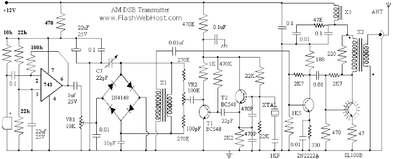 AM Transmitter Double Side Band


