Showing posts with label fm. Show all posts

Thursday, July 4, 2013

Use LA1800 Portable AM and FM Radio

This portable AM and FM radio circuit is designed using the LA1800 IC and some other external components. As you can see in this circuit diagram the LA1800 manufactured by Sanyo Semiconductors , require few additional components. The LA1800 am FM portable radio circuit needs to be powered from a 3 volt DC power supply circuit.


You can use an 3 volt battery. This radio receiver circuit has a low current dissipation of 5.6mA for FM band and 3.2mA for AM band .Also the output signal is driven into earphone speakers , but you can use an additional speaker ( in that case you need to connect an additional small power audio amplifier).
{ Read More }


Wednesday, June 12, 2013

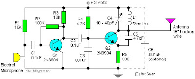
Sensitive FM Transmitter circuit diagram

Sensitive FM Transmitter circuit diagram

Simple and easy build of FM transmitter circuit. The circuit only require 2 transistors.


Circuit Notes:
Typically the default for the capacitors model is ceramic, preferably the npo 1% type or equivalent. However , generally almost nothing critical right here. Work with any capacitor you’ve laying arround, but DO NOT use any electrolytic or tantalum capacitors. Only in case you intend to apply this circuit outside the home you may need to use capacitores which have more temperature stability.

{ Read More }


Friday, May 17, 2013

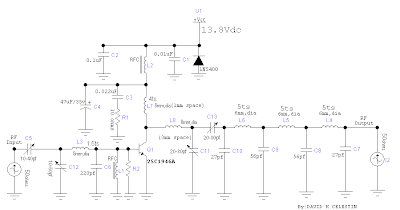
30W VHF FM Broadcast Amplifier

The 30 watt amplifier circuit shown below provides an appropriate power boost with an input of 4 watt up to 6 watts. The circuit is designed to cover 88-108MHz FM Broadcast Band. However, the circuit is very stable at my place and provides a clean-output through seven (7) element Butter-worth low-pass filter.
30W VHF FM Broadcast Amplifier
The heart of the circuit is 2SC1946A VHF RF power transistor. The transistor is specifically designed to operate at frequencies up to 175 MHz, with very good results.

The feedline is decoupled. The current amplifier can be more than 5 amps. All coils are made of 16gauge wire rod (copper or silver wire can do better) and HF RFC may be central torus (as shown in the image) or 6-hole ferrite R1 bead.C3 and snubber circuit forms, while R2 and C6 prevent the amplifier self-oscillation in VHF, it is sometimes necessary to add 180 ohms in parallel with the amplifier will L7.That to dispel UNDESIRABLE VHF thereby reduce the spurious level.

The 60Watts VHF power amplifier using the above circuit. 2SC1946A Two transistors are arranged at 90 degrees to each other and their results were combined using "Network Power Combiner". It is very difficult to combine skills in the VHF and UHF

{ Read More }


IconIconIconFollow Me on Pinterest