Showing posts with label sensitive. Show all posts

Wednesday, July 10, 2013

Touch Sensitive Alarm Circuit Diagram


Description

                Circuit showing a Touch Sensitive Alarm .Here i have used bc 548 transistor for switching and bc 107 for sound generation
.You need a power supply

Click here to view the power supply circuit diagram

Components Required

 Resistor

            680R ,100 K

 Transistor

             BC 548, BC 107 - 2

Loud Speaker

Copper plate
Source by : http://www.electronics-circuits.in/2012/03/touch-sensitive-alarm-circuit-diagram.html#more
{ Read More }


Saturday, July 6, 2013

Dark Sensitive Power Switch Circuit Diagram Using LDR


Description

Circuit showing a Dark Sensitive Power Switch .Here we have used a ldr and a ordinary transistor for making this circuit
.Connect any 230 volt equipment at the load .You need a 9 volt power supply
Components Required

         Resistor

                     10 k , 680 R

          Transistor

                        BC 548

          Diode

                   IN 4007

         Relay

         LDR
{ Read More }


Wednesday, June 12, 2013

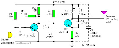
Sensitive FM Transmitter circuit diagram

Sensitive FM Transmitter circuit diagram

Simple and easy build of FM transmitter circuit. The circuit only require 2 transistors.


Circuit Notes:
Typically the default for the capacitors model is ceramic, preferably the npo 1% type or equivalent. However , generally almost nothing critical right here. Work with any capacitor you’ve laying arround, but DO NOT use any electrolytic or tantalum capacitors. Only in case you intend to apply this circuit outside the home you may need to use capacitores which have more temperature stability.

{ Read More }


Saturday, March 30, 2013

Dew Sensitive Switch Circuit Using LM358

This is a simple design circuit that can be used to switch ON or OFF a device when the dew present in the surrounding atmosphere crosses a set value. This circuit uses a dew sensitive resistive element and a comparator based on LM 358 to perform the above said operation. This is the figure of the circuit.


In operation of the circuit, at normal condition the resistance of dew sensor element will be low and so the voltage drop across it. So the voltage at the non inverting pin of LM358 (IC1) will be less than the voltage at the inverting input of the LM358.So the output of the op amp will be low. This keeps the opto coupler (MCT2E) deactivated. When the dew increases the resistance of the element increases and so do the voltage across it. Now the voltage at the non inverting pin of LM358 (IC1) will be higher than the voltage at the inverting input of the LM358.So the output of the op amp will be switched to high. This in turn activates the opto coupler. The LED glows to indicate it. As a result we get an opto coupler activated and de activated according to the amount of dew in the atmosphere. The output pins of opto coupler pin (5&4) can be used to control the external device.

Diode D1, resistors R6&R3 and capacitor C1 is employed here to derive the power for the circuit directly from mains. The dew sensor is hard to find in market. But it can be easily obtained from a old VCR. Also the type no of the sensor is not so important here. Try with any thing you get. I used one from a old Hitachi VCR. LM 358 is a dual op amp. Here only one op amp inside it is used.

{ Read More }


IconIconIconFollow Me on Pinterest