Showing posts with label switch. Show all posts

Sunday, August 4, 2013

Green USB switch

According to the Energy Saving  Trust, if you add up all the current drawn in standby mode by items such as stereos, TVs, VCRs and DVDs over a year in the UK alone, it amounts to 3.1 million tonnes of CO2 released into the atmosphere.This is without factoring in the current drawn by all the PCs,laptops and their associated peripherals left in standby mode. 

Circuit diagram :
Green USB switch-Circuit Diagram
Green USB switch Circuit Diagram

It  is  not  necessary  to  spend  a  great deal of money or time to  make a difference on a personal  level. The circuit described here  is designed for use by laptop or  notebook computers. It will automatically switch off all mains  powered peripheral equipment  including monitor, printer, scanner, TV tuner and USB hub etc  when it detects that the notebook  is switched off. The circuit is quite  straightforward; in addition to an  optocoupler it requires a 12 V  double-pole  relay  with  mains  rated contacts and a small power  supply  for  the  optocoupler.  When the laptop is switched on  5 V appears at the USB socket,  activating the relay and switching  through  the  mains  supply  on K3 and K4. The notebook’s  USB socket is still available to be  used as normal but it’s worth remembering that the optocoupler  takes a few milliamps from the  USB supply and this may cause a  problem if a high-current device  is plugged into the USB socket.  In the case where the laptop has  more than enough USB sockets it may be worthwhile us-ing one of them solely for this  circuit, the extension USB connector K2 would then not be  required. 

The circuit is mounted into a  mains plug enclosure which  provides a socket where the  mains extension strip will be  plugged into. With any luck  there will be sufficient space  to fit the entire circuit into the  mains extension strip enclosure and save the need for a  separate enclosure. The slow-blow 6.3-A fuse (F1) protects  the equipment plugged into  the strip. 

In  addition  to  the  optocoupler  and relay the circuit also has a  ‘freewheel’ diode D1 and a relay  driver formed by T1 and its base  bias voltage divider network R2/ R4. The two ‘snubber’ networks  C1/R3 and C2/R5 reduce the  possibility of arcing which can  occur  when  the  relay  contacts  open (especially with inductive  loads). Capacitors C1 and C2  must be class X2 types which  can handle mains voltage plus any  spikes.  The  power  supply  consists of a small mains trans-former  (12 V,  50 mA),  bridge  rectifier and smoothing capacitor C3. 

The laptop’s mains adaptor itself  can also be switched by this circuit when the laptop is fitted with  its rechargeable battery which  allows the computer to boot up  without a mains supply. The en-tire USB switch circuit draws cur-rent even when it is off but this value  is  tiny  compared  to  the  combined standby current of all  the peripherals. 

Note that parts of this circuit are  connected to the (potentially lethal) mains supply voltage; it is  essential to provide protection  to ensure that nothing can accidentally make contact with these  parts of the circuit. It is also important to observe correct separation between parts of the circuit carrying low voltage and  those carrying the high volt-age. Please observe the electrical Electrical Safety guide-lines which are reprinted in  Elektor  Electronics  several  times a year. 

The  circuit  is  less  suitable  for use with desktop PCs be-cause  the  majority  of  these  machines supply 5 V over the  USB socket even though they  have been shut down via soft-ware. The only way to turn off  in this case is to reach around  the back of the machine and  switch off at the main switch. 


http://streampowers.blogspot.com/2012/06/green-usb-switch.html
{ Read More }


Friday, July 12, 2013

Low Voltage Remote Mains Switch

This circuit allows a 240V mains appliance to be controlled remotely via low-voltage cabling and a pushbutton switch. The mains appliance (in this case, a light bulb) is switched with a suitably-rated relay. All of the electronics is housed in an ABS box located in proximity to the appliance. The pushbutton switch and plugpack are located remotely and can be wired up with 3-core alarm cable or similar. Cable lengths of 20m or more are feasible with this arrangement. When the switch (S1) is pressed, the input (pin 8) of IC1c is briefly pulled low via the 10mF capacitor, which is initially discharged.

Circuit diagram:
low-voltage-remote-mains-switch-circuit-diagramw
Low-Voltage Remote Mains Switch Circuit Diagram

The output (pin 10) immediately goes high and this is inverted and fed back to the second input (pin 9) via another gate in the quad NAND package (IC1d). In conjunction with the 1MW resistor and 470nF capacitor, IC1d eliminates the effects of contact "bounce" by ensuring that IC1c’s output remains high for a predetermined period. The output from IC1c drives the clock input of a 4013 D-type flip-flop (IC2). The flipflop is wired for a "toggle" function by virtue of the Q-bar connection back to the D input. A 2.2MW resistor and 100nF capacitor improve circuit noise immunity. Each time the switch is pressed, the flipflop output (pin 13) toggles, switching the transistor (Q1) and relay on or off. Note that all mains wiring must be properly installed and completely insulated so that there is no possibility of it contacting the low-voltage side of the circuit.
 
 
http://streampowers.blogspot.com/2012/06/low-voltage-remote-mains-switch.html
{ Read More }


Control Switch for Fan and Air Conditioner

An electronic switch that can be used to switch on both the air-conditioner as well as fan of your room, one by one. The circuit consists of power supply and control sections. The power supply section is built around transformer X1, bridge rectifier BR1 and filter capacitor C1. The 50Hz, 230V AC mains is stepped down by transformer X1 to deliver a secondary output of 9V, 300 mA. The transformer output is rectified by the bridge rectifier and filtered by capacitor C1.


When the mains is switched on for the first time, pin 3 of IC CD4017 (IC1) goes high and relay RL1 energies to switch on the fan. When mains is briefly switched off using S1 and then switched on, the power to IC1 is maintained by the charge on capacitor C1. At the same time, there is a trigger pulse on the clock input (pin 14) of IC1, which advances the decade counter and relay RL2 energies to switch-on the air-conditioner. Both the air-conditioner and the fan will be turned off if the switch is in the ‘off’ position.

Assemble the circuit on a general-purpose PCB and enclose in a suitable case. Fix the unit onto the switchboard. Use relays RL1 and RL2 with proper contact ratings. The current rating depends on the load that you are going to control.
{ Read More }


Wednesday, July 10, 2013

Automatic TV Lighting Switch

The author is the happy owner of a television set with built-in Ambilight lighting in the living room. Unfortunately, the television set in  the bedroom lacks this feature. To make up for this, the author attached a small lamp to the wall to provide background lighting, This makes  watching television a good deal more enjoyable, but it ’s  not the ideal solution. Although the TV set can be  switched off with the remote  control, you still have to get out of bed to switch off the lamp.

Circuit diagram :
Automatic TV Lighting Switch-Circuit-Diagram

Automatic TV Lighting Switch Circuit Diagram

Consequently, the author devised this automatic lighting switch that switches the background light on and off along with the T V set. The entire circuit is fitted in series with the mains cable of the TV set, so there’s no need to tinker with the set. It works as follows: R1 senses  the current drawn by the TV  set. It has a maximum value  of 50 mA in standby mode,  rising  to around   500 m A  when  the  set  is  operating. The voltage across R1 is limited by D5 during negative  half- cycles  and  by  D1– D4  during positive half-cycles.  T he  voltage  across  these  four diodes charges capacitor C1 via D6 during positive  half-cycles. This voltage drives the internal LED of solid-state switch TRI1 via R2, which causes the internal triac to conduct and pass the mains voltage to the lamp.   Diode D7 is not absolutely necessary, but  it is recommended because the LED in the  solid-state switch is not especially robust  and cannot handle reverse polarisation. Fuse  F1 protects the solid-state switch against  overloads. T he  value  of  use d  here  (10 Ω)  for  resistor R1 works nicely with an 82-cm (32 inch)  LCD screen.

With smaller sets having lower  power consumption, the value of R1 can be  increased to 22 or 33 Ω, in which case you  should use a 3-watt type. Avoid using an  excessively high resistance, as otherwise TRI1 will switch on when the TV set is in standby mode.  Some TV sets have a half-wave rectifier in the  power supply, which places an unbalanced  load on the AC power outlet. If the set only  draws current on negative half-cycles, the cir-cuit won’t work properly. In countries with  reversible AC power plugs you can correct  the problem by simply reversing the plug. Compared with normal triacs, optically cou-pled solid-state relays have poor resistance  to high switch-on currents (inrush currents).

For this reason, you should be careful with  older-model TV sets with picture tubes (due  to demagnetisation circuits). If the relay fails,  it usually fails shorted, with the result that the TV background light remains on all the time. If you build this circuit on a piece of perf-board, you must remove all the copper next  to conductors and components carrying  mains voltage. Use PCB terminal blocks with a spacing of 7.5 mm. This way the separation between the connections on the solder  side will also be 3 mm. If you fit the entire  arrangement as a Class II device, all parts of  the circuit at mains potential must have a  separation of at least 6 mm from any metal  enclosure or electrically conductive exterior  parts that can be touched. 


http://streampowers.blogspot.com/2012/06/automatic-tv-lighting-switch_11.html 
{ Read More }


Tuesday, July 9, 2013

Battery Switch With Low Dropout Regulator

In the form of the LT1579 Linear Technology (www.linear-tech.com) has produced a practical battery switch with an integrated low-dropout regulator. In contrast to previous devices no diodes are required. The circuit is available in a 3.3 V version (LT1579CS8-3.3) and in a 5 V version (LT1579CS8-5), both in SO8 SMD packages. There is also an adjustable version and versions in an SO16 package which offer a greater range of control and drive signals. The main battery, whose terminal voltage must be at least 0.4 V higher than the desired output voltage, is connected to pin IN1. The backup battery is connected to pin IN2. The regulated output OUT can deliver a current of up to 300 mA. The LDO regulator part of the IC includes a pass transistor for the main input voltage IN1 and another for the backup battery on IN2.

Battery_Switch_With_LDO_Regulator_Circuit_Diagramw

The IC will switch over to the backup battery when it detects that the pass transistor for the main voltage input is in danger of no longer being able to maintain the required output voltage. The device then smoothly switches over to the backup battery. The open-drain status output BACKUP goes low to indicate when this has occurred. When neither battery is able to maintain the output voltage at the desired level the open-drain output DROPOUT goes low. The LT1579 can operate with input voltages of up to +20 V from the batteries. The regulator output OUT is short-circuit proof. The shutdown input switches off the output; if this feature is not required, the input can simply be left open.
 
 
Streampowers
{ Read More }


Monday, July 8, 2013

Green USB switch

According to the Energy Saving  Trust, if you add up all the current drawn in standby mode by items such as stereos, TVs, VCRs and DVDs over a year in the UK alone, it amounts to 3.1 million tonnes of CO2 released into the atmosphere.This is without factoring in the current drawn by all the PCs,laptops and their associated peripherals left in standby mode. 

Circuit diagram :
Green USB switch-Circuit Diagram
Green USB switch Circuit Diagram

It  is  not  necessary  to  spend  a  great deal of money or time to  make a difference on a personal  level. The circuit described here  is designed for use by laptop or  notebook computers. It will automatically switch off all mains  powered peripheral equipment  including monitor, printer, scanner, TV tuner and USB hub etc  when it detects that the notebook  is switched off. The circuit is quite  straightforward; in addition to an  optocoupler it requires a 12 V  double-pole  relay  with  mains  rated contacts and a small power  supply  for  the  optocoupler.  When the laptop is switched on  5 V appears at the USB socket,  activating the relay and switching  through  the  mains  supply  on K3 and K4. The notebook’s  USB socket is still available to be  used as normal but it’s worth remembering that the optocoupler  takes a few milliamps from the  USB supply and this may cause a  problem if a high-current device  is plugged into the USB socket.  In the case where the laptop has  more than enough USB sockets it may be worthwhile us-ing one of them solely for this  circuit, the extension USB connector K2 would then not be  required. 

The circuit is mounted into a  mains plug enclosure which  provides a socket where the  mains extension strip will be  plugged into. With any luck  there will be sufficient space  to fit the entire circuit into the  mains extension strip enclosure and save the need for a  separate enclosure. The slow-blow 6.3-A fuse (F1) protects  the equipment plugged into  the strip. 

In  addition  to  the  optocoupler  and relay the circuit also has a  ‘freewheel’ diode D1 and a relay  driver formed by T1 and its base  bias voltage divider network R2/ R4. The two ‘snubber’ networks  C1/R3 and C2/R5 reduce the  possibility of arcing which can  occur  when  the  relay  contacts  open (especially with inductive  loads). Capacitors C1 and C2  must be class X2 types which  can handle mains voltage plus any  spikes.  The  power  supply  consists of a small mains trans-former  (12 V,  50 mA),  bridge  rectifier and smoothing capacitor C3. 

The laptop’s mains adaptor itself  can also be switched by this circuit when the laptop is fitted with  its rechargeable battery which  allows the computer to boot up  without a mains supply. The en-tire USB switch circuit draws cur-rent even when it is off but this value  is  tiny  compared  to  the  combined standby current of all  the peripherals. 

Note that parts of this circuit are  connected to the (potentially lethal) mains supply voltage; it is  essential to provide protection  to ensure that nothing can accidentally make contact with these  parts of the circuit. It is also important to observe correct separation between parts of the circuit carrying low voltage and  those carrying the high volt-age. Please observe the electrical Electrical Safety guide-lines which are reprinted in  Elektor  Electronics  several  times a year. 

The  circuit  is  less  suitable  for use with desktop PCs be-cause  the  majority  of  these  machines supply 5 V over the  USB socket even though they  have been shut down via soft-ware. The only way to turn off  in this case is to reach around  the back of the machine and  switch off at the main switch. 


http://streampowers.blogspot.com/2012/06/green-usb-switch.html
{ Read More }


Saturday, July 6, 2013

Dark Sensitive Power Switch Circuit Diagram Using LDR


Description

Circuit showing a Dark Sensitive Power Switch .Here we have used a ldr and a ordinary transistor for making this circuit
.Connect any 230 volt equipment at the load .You need a 9 volt power supply
Components Required

         Resistor

                     10 k , 680 R

          Transistor

                        BC 548

          Diode

                   IN 4007

         Relay

         LDR
{ Read More }


Clap Switch Circuit Diagram

Here’s a clap switch free from false triggering. To turn on/off any appliance, you just have to clap twice. The circuit changes its output state only when you clap twice within the set time period. Here, you’ve to clap within 3 seconds. 

The clap sound sensed by condenser microphone is amplified by transistor T1. The amplified signal provides negative pulse to pin 2 of IC1 and IC2, triggering both the ICs. IC1, commonly used as a timer, is wired here as a monostable multivibrator. Trigging of IC1 causes pin 3 to go high and it remains high for a certain time period depending on the selected values of R7 and C3. 

This ‘on’ time (T) of IC1 can be calculated using the following relationship: T=1.1R7.C3 seconds where R7 is in ohms and C3 in microfarads. On first clap, output pin 3 of IC1 goes high and remains in this standby position for the preset time.Also, LED1 glows for this period. The output of IC1 provides supply voltage to IC2 at its pins 8 and 4.
Circuit diagram :
Clap Switch  Circuit Diagram
Clap Switch Circuit Diagram

Now IC2 is ready to receive the triggering signal. Resistor R10 and capacitor C7 connected to pin 4 of IC2 prevent false triggering when IC1 provides the supply voltage to IC2 at first clap. On second clap, a negative pulse triggers IC2 and its output pin 3 goes high for a time period depending on R9 and C5.

 This provides a positive pulse at clock pin 14 of decade counter IC 4017 (IC3). Decade counter IC3 is wired here as a bistable. Each pulse applied at clock pin 14 changes the output state at pin 2 (Q1) of IC3 because Q2 is connected to reset pin 15. The high output at pin 2 drives transistor T2 and also energizes relay RL1. LED2 indicates activation of relay RL1 and on/off status of the appliance. A free-wheeling diode (D1) prevents damage of T2 when relay de-energizes.
 
 
http://streampowers.blogspot.com/2012/06/clap-switch-circuit-diagram.html
{ Read More }


Monday, June 3, 2013

Wiringdouble Light Switch Diagramelectrical Information Blog

Light Switch Wiring on Wiring Diagram   I Took Some Photos Of The Wiring Mess Before I
Wiring Diagram I Took Some Photos Of The Wiring Mess Before I.


Light Switch Wiring on Review Of Switched Outlet Wiring  Power Enters At The Outlet
Review Of Switched Outlet Wiring Power Enters At The Outlet.


Light Switch Wiring on Wiring A Double Light Switch Diagram   Electrical Information Blog
Wiring A Double Light Switch Diagram Electrical Information Blog.


Light Switch Wiring on Wiring Clipsal Saturn Light Switches 2 Way Switch Wiring Diagram Jpg
Wiring Clipsal Saturn Light Switches 2 Way Switch Wiring Diagram Jpg.


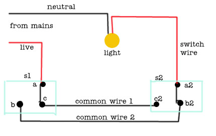
Light Switch Wiring on Two Way Light Switch Wiring
Two Way Light Switch Wiring.


Light Switch Wiring on Power Light Switch Switch
Power Light Switch Switch.


Light Switch Wiring on Light Switch Wiring Diagram Uk   Reviews And Photos
Light Switch Wiring Diagram Uk Reviews And Photos.


Light Switch Wiring on Three Way Light Switch Wiring
Three Way Light Switch Wiring.


Light Switch Wiring on How To Wire A Switch   Light Then Switch And Outlet
How To Wire A Switch Light Then Switch And Outlet.


Light Switch Wiring on Light Switch Wiring Headlight Switch Diagram Jpg
Light Switch Wiring Headlight Switch Diagram Jpg.


{ Read More }


Friday, May 31, 2013

Light Outlet Switch Wiring Diagram

Light Switch Wiring on Light Switch In Your Home    By Tara Gilbert Wiring A Light Switch Is
Light Switch In Your Home By Tara Gilbert Wiring A Light Switch Is.


Light Switch Wiring on Light With Outlet 2 Way Switch Wiring Diagram
Light With Outlet 2 Way Switch Wiring Diagram.


Light Switch Wiring on How To Wire A Switch   Switch And Light At End Of Circuit
How To Wire A Switch Switch And Light At End Of Circuit.


Light Switch Wiring on Like The Diagram Above  Power Switch Switch Light
Like The Diagram Above Power Switch Switch Light.


Light Switch Wiring on Way As It Is The Easiest Light Switch Wiring Scenario
Way As It Is The Easiest Light Switch Wiring Scenario.


Light Switch Wiring on How To Install Light Switches   Hometips
How To Install Light Switches Hometips.


Light Switch Wiring on How To Wire A Switch   Light Then Switch At End Of Circuit
How To Wire A Switch Light Then Switch At End Of Circuit.


Light Switch Wiring on Light Switch Wiring Diagram
Light Switch Wiring Diagram.


Light Switch Wiring on Light And Outlet 2 Way Switch Wiring Diagram
Light And Outlet 2 Way Switch Wiring Diagram.


Light Switch Wiring on End Of The Corridor And You Want To Switch Off The Light The Switch
End Of The Corridor And You Want To Switch Off The Light The Switch.


{ Read More }


Monday, May 27, 2013

Basic Switch Wiring Diagram

Wiring Diagram on In Pairs Above Is A Simple Schematic Diagram Of How The Wiring For
In Pairs Above Is A Simple Schematic Diagram Of How The Wiring For.


Wiring Diagram on Installing A Tachometer In Your Ford Ranger
Installing A Tachometer In Your Ford Ranger.


Wiring Diagram on Schematic Diagram
Schematic Diagram.


Wiring Diagram on Wiring Diagram Symbols
Wiring Diagram Symbols.


Wiring Diagram on Dodge Dakota Radio Wiring Diagram 1998 Dodge Ram 1500 Wiring Diagram
Dodge Dakota Radio Wiring Diagram 1998 Dodge Ram 1500 Wiring Diagram.


Wiring Diagram on Basic Thermostat Wiring Diagram
Basic Thermostat Wiring Diagram.


Wiring Diagram on Basic 2 Way Switch Wiring Diagram
Basic 2 Way Switch Wiring Diagram.


Wiring Diagram on Trailer Wiring Diagram Trailer Plug Diagram
Trailer Wiring Diagram Trailer Plug Diagram.


Wiring Diagram on Post It But I Ll Try To Diagram It Here
Post It But I Ll Try To Diagram It Here.


Wiring Diagram on The Following Schematic Shows A Typical Diagram Schematic Of Polaris
The Following Schematic Shows A Typical Diagram Schematic Of Polaris.


{ Read More }


Tuesday, May 14, 2013

Wire Lights Controlled Switch

Wiringlight on Wiring Trailer Lights
Wiring Trailer Lights.


Wiringlight on Wiring A Light Fitting
Wiring A Light Fitting.


Wiringlight on Headlight Wiring   12 Volt Lights On A 24 Volt System   Service
Headlight Wiring 12 Volt Lights On A 24 Volt System Service.


Wiringlight on Wiring A Switch With Light In Middle Of Circuit
Wiring A Switch With Light In Middle Of Circuit.


Wiringlight on Light With Outlet 2 Way Switch Wiring Diagram
Light With Outlet 2 Way Switch Wiring Diagram.


Wiringlight on Thread  Wiring Clipsal Saturn Light Switches
Thread Wiring Clipsal Saturn Light Switches.


Wiringlight on The Method I Used For Wiring The Lights For The
The Method I Used For Wiring The Lights For The.


Wiringlight on How To Wire Two Lights Controlled From One Switch
How To Wire Two Lights Controlled From One Switch.


Wiringlight on How To Towbar Wiring 12n 12s Fitting Guides
How To Towbar Wiring 12n 12s Fitting Guides.


Wiringlight on Way Switch Wiring Diagram Variation  3   Electrical Online
Way Switch Wiring Diagram Variation 3 Electrical Online.
{ Read More }


Wednesday, May 8, 2013

Ultrasonic switch

circuit of a new type of remote control switch is described here. This circuit functions with inaudible (ultrasonic) sound. Sound of frequency up to 20 kHz is audible to human beings. The sound of frequency above 20 kHz is called ultrasonic sound. The circuit described generates (transmits) ultrasonic sound of frequency between 40 and 50 kHz. As with any other remote control system this cirucit too comprises a mini transmitter and a receiver circuit. Transmitter generates ultrasonic sound and the receiver senses ultrasonic sound from the transmitter and switches on a relay. The ultrasonic transmitter uses a 555 based astable multivibrator. It oscillates at a frequency of 40-50 kHz. An ultrasonic transmitter transducer is used here to transmit ultrasonic sound very effectively.

The transmitter is powered from a 9-volt PP3 single cell. The ultrasonic receiver circuit uses an ultrasonic receiver transducer to sense ultrasonic signals. It also uses a two-stage amplifier, a rectifier stage, and an operational amplifier in inverting mode. Output of op-amp is connected to a relay through a complimentary relay driver stage. A 9-volt battery eliminator can be used for receiver circuit, if required. When switch S1 of transmitter is pressed, it generates ultrasonic sound. The sound is received by ultrasonic receiver transducer. It converts it to electrical variations of the same frequency. These signals are amplified by transistors T3 and T4.

The amplified signals are then rectified and filtered. The filtered DC voltage is given to inverting pin of op-amp IC2. The non- inverting pin of IC2 is connected to a variable DC voltage via preset VR2 which determines the threshold value of ultrasonic signal received by receiver for operation of relay RL1. The inverted output of IC2 is used to bias transistor T5. When transistor T5 conducts, it supplies base bias to transistor T6. When transistor T6 conducts, it actuates the relay. The relay can be used to control any electrical or electronic equipment. Important hints:

1. Frequency of ultrasonic sound generated can be varied from 40 to 50 kHz range by adjusting VR1.
Adjust it for maximum performance.

2. Ultrasonic sounds are highly directional. So when you are operating the switch the ultrasonic transmitter transducer of transmitter should be placed towards ultrasonic receiver transducer of receiver circuit for proper functioning.

3. Use a 9-volt PP3 battery for transmitter. The receiver can be powered from a battery eliminator and is always kept in switched on position.

4. For latch facility use a DPDT relay if you want to switch on and switch off the load. A flip-flop can be inserted between IC2 and relay. If you want only an ‘ON-time delay’ use a 555 only at output of IC2. The relay will be energised for the required period determined by the timing components of 555 monostable multivibrator.

5. Ultrasonic waves are emitted by many natural sources. Therefore, sometimes, the circuit might get falsely triggered, espically when a flip-flop is used with the circuit, and there is no remedy for that
http://www.electronic-circuits-diagrams.com/sensorsimages/7.gif
{ Read More }


Sunday, April 21, 2013

USB Switch Schematic Circuit

Anyone experimenting or developing USB ported peripheral hardware soon be comes irritated by the need to disconnect and connect the plug  in order to reestablish communication with the PC. This process is necessary for example each time the peripheral equipment is reset or a new version of the firmware is installed. As well as tiresome it eventually leads to excessive contact wear in the USB connector. The answer is to build this electronic isolator which disconnects the peripheral device at the touch of a button. This is guaranteed to reduce any physical wear and tear and restore calm once again to the workplace. 

Circuit image :
 USB Switch-Image
USB Switch Schematic Circuit Image

The circuit uses a quad analogue switch type 74HC4066. Two of the switches in the package are used to isolate the data path. The remaining two are used in a classic bistable flip-flop configuration which is normally built using transistors. A power MOSFET switches the power supply current to the USB device.  Capacitor C2 ensures that the flip flop always  powers-up in a defined state when plugged  into the USB socket (‘B’ in the diagram). 

The  peripheral device connected to USB socket ‘A’  will therefore always be ‘not connected’ until  pushbutton S2 is pressed. This flips the bistable, turning on both analogue gates in the data lines and switching the MOSFET on. The  PC now recognises the USB device. Pressing  S1 disconnects the device.
Circuit diagram :
USB Switch-Circuit-daigram
USB Switch Schematic Circuit Diagram

The circuit does not sequence the connections as a physical USB connector does; the power supply connection strips are slightly longer than the two inner data carrying strips to ensure the peripheral receives power before the data signals are connected. The electronic switch does not suffer from the same contact problems as the physical  connector so these measures are not required in the circuit. The  simple circuit can quite easily be constructed on a small  square of perforated strip-board. 

The design uses the 74HC(T)4066 type analogue switch, these have  better characteristics compared to the standard 4066 device. The USB switch is suitable for both low-speed (1.5 MBit/ s) and full-speed (12 MBit/s) USB ports applications but the proper ties of the analogue switches and perf-board construction  will not support hi-speed (480 MBit/s) USB operation. 

The IRFD9024 MOSFET can pass a current of  up to 500 mA to the peripheral device with-out any problem.


Source : www.ecircuitslab.com
{ Read More }


IconIconIconFollow Me on Pinterest