Showing posts with label control. Show all posts

Monday, December 23, 2013

Automatic Room Power Control


          An ordinary automatic room power control circuit has only one light sensor. So when a person enters the room it gets one pulse and the lights come ‘on.’ When the person goes out it gets another pulse and the lights go ‘off.’ But what happens when two persons enter the room, one after the other? It gets two pulses and the lights remain in ‘off’ state. The circuit described here overcomes the above-mentioned problem. It has a small memory which enables it to automatically switch ‘on’ and switch ‘off’ the lights in a desired fashion.

www.blogger.com

   The circuit uses two LDRs which are placed one after another (separated by a distance of say half a metre) so that they may separately sense a person going into the room or coming out of the room. Outputs of the two LDR sensors, after processing, are used in conjunction with a bicolour LED in such a fashion that when a person gets into the room it emits green light and when a person goes out of the room it emits red light, and vice versa. These outputs are simultaneously applied to two counters.

   One of the counters will count as +1, +2, +3 etc when persons are coming into the room and the other will count as -1, -2, -3 etc when persons are going out of the room. These counters make use of Johnson decade counter CD4017 ICs. The next stage comprises two logic ICs which can combine the outputs of the two counters and determine if there is any person still left in the room or not.

   Since in the circuit LDRs have been used, care should be taken to protect them from ambient light. If desired, one may use readily available IR sensor modules to replace the LDRs. The sensors are installed in such a way that when a person enters or leaves the room, he intercepts the light falling on them sequentially—one after the other.

   When a person enters the room, first he would obstruct the light falling on LDR1, followed by that falling on LDR2. When a person leaves the room it will be the other way round. In the normal case light keeps falling on both the LDRs, and as such their resistance is low (about 5 kilo-ohms). As aresult, pin 2 of both timers (IC1 and IC2), which have been configured as monostable flip-flops, are held near the supply voltage (+9V).

   When the light falling on the LDRs is obstructed, their resistance becomes very high and pin 2 voltages drop to near ground potential, thereby triggering the flip-flops. Capacitors across pin 2 and ground have been added to avoid false triggering due to electrical noise.

   When a person enters the room, LDR1 is triggered first and it results in triggering of monostable IC1. The short output pulse immediately charges up capacitor C5, forward biasing transistor pair T1-T2. But at this instant the collectors of transistors T1 and T2 are in high impedance state as IC2 pin 3 is at low potential and diode D4 is not conducting.

   But when the same person passes LDR2, IC2 monostable flip-flop is triggered. Its pin 3 goes high and this potential is coupled to transistor pair T1-T2 via diode D4. As a result transistor pair T1-T2 conducts because capacitor C5 retains the charge for some time as its discharge time is controlled by resistor R5 (and R7 to an extent). Thus green LED portion of bi-colour LED is lit momentarily.

   The same output is also coupled to IC3 for which it acts as a clock. With entry of each person IC3 output (high state) keeps advancing. At this stage transistor pair T3-T4 cannot conduct because output pin 3 of IC1 is no longer positive as its output pulse duration is quite short and hence transistor collectors are in high impedance state.

   When persons leave the room, LDR2 is triggered first, followed by LDR1. Since the bottom half portion of circuit is identical to top half, this time, with the departure of each person, red portion of bicolour LED is lit momentarily and output of IC4 advances in the same fashion as in case of IC3.

   The outputs of IC3 and those of IC4 (after inversion by inverter gates N1 through N4) are ANDed by AND gates (A1 through A4) and then wire ORed (using diodes D5 through D8). The net effect is that when persons are entering, the output of at least one of the AND gates is high, causing transistor T5 to conduct and energise relay RL1. The bulb connected to the supply via N/O contact of relay RL1 also lights up.

   When persons are leaving the room, and till all the persons who entered the room have left, the wired OR output continues to remain high, i.e. the bulb continues to remains ‘on,’ until all persons who entered the room have left.

   The maximum number of persons that this circuit can handle is limited to four since on receipt of fifth clock pulse the counters are reset. The capacity of the circuit can be easily extended to handle up to nine persons by removing the connection of pin 1 from reset pin (15) and utilising Q1 to Q9 outputs of CD4017 counters. Additional inverters, AND gates and diodes will, however, be required.


{ Read More }


Friday, July 12, 2013

Remote Control Receiver

Hello! in this post I will show a remote control receiver, I tested this circuit with an approximate distance of 4 meters and it worked perfectly, the spread of this circuit is that it can be triggered by remote control of multiple devices, I tested with two remote controls one tV receiver and a satellite dish, every time you press a key on the remote, the LED will light up and trigger the relay, the relay output you can connect any device you want to control the 1N4148 diode D4 is also You can add more channels to the circuit, just by connecting the reset of the integrated circuit in 4017 and adding another exit other relés.Assim each pulse sent to the receiver, trigger a relay!

The relay coil has voltage according to the circuit power!

See the figure below:


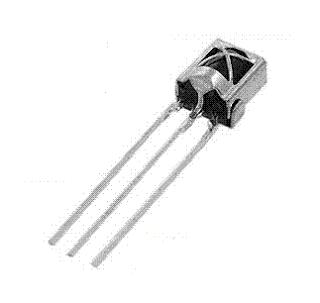
The receiver used is three terminals, commonly used in television sets!

See the figure below:

{ Read More }


Control Switch for Fan and Air Conditioner

An electronic switch that can be used to switch on both the air-conditioner as well as fan of your room, one by one. The circuit consists of power supply and control sections. The power supply section is built around transformer X1, bridge rectifier BR1 and filter capacitor C1. The 50Hz, 230V AC mains is stepped down by transformer X1 to deliver a secondary output of 9V, 300 mA. The transformer output is rectified by the bridge rectifier and filtered by capacitor C1.


When the mains is switched on for the first time, pin 3 of IC CD4017 (IC1) goes high and relay RL1 energies to switch on the fan. When mains is briefly switched off using S1 and then switched on, the power to IC1 is maintained by the charge on capacitor C1. At the same time, there is a trigger pulse on the clock input (pin 14) of IC1, which advances the decade counter and relay RL2 energies to switch-on the air-conditioner. Both the air-conditioner and the fan will be turned off if the switch is in the ‘off’ position.

Assemble the circuit on a general-purpose PCB and enclose in a suitable case. Fix the unit onto the switchboard. Use relays RL1 and RL2 with proper contact ratings. The current rating depends on the load that you are going to control.
{ Read More }


Wednesday, July 10, 2013

IR Remote Control Extender Mark 3

This Mark3 version of the Infra Red extender is a special version designed to control appliances that use high frequency modulated IR remote controls.


Notes:
IR appliances use pulses (control signals) sent over a modulated IR carrier wave. The carrier wave may be modulated at various frequencies, 36-38KHz being the most popular.Some Satellite receivers use even higher frequencies than this. The IR1 remote module receives an infra red signal and separates control pulses from the modulation. To re-transmit, a 555 timer is configured as an astable oscillator. The 555 timer is controlled by the signal on the reset pin, high generating a carrier and low no carrier. Each control pulse turns on the oscillator for the duration of a logic high signal and off for a logic 0 signal, thereby creating a newly modulated IR signal. The IR module, part number IR1 is available from Harrison Electronics in the UK, IR1 may not be listed in their catalogue but if you ask for an IR1, they will send you the correct part. The IR1 arrives in a small aluminium case, the connections viewed from underneath are shown below:

Infra Red Module, IR1 Pinout

Harrison Electronics have limited supplies of the IR1 but as a replcement a standard IR module like the TSOP1838 may be used. The pinout is shown below:


The carrier frequency is determined by R1 and C3, values shown work at 39.7 kHz, but these may be altered to provide different carrier frequencies. The final CMOS 4049 invertor ensures that under "no signal" conditions both LEDs are also off.

Parts List:

C1 100u 10V
C2 100n polyester
C3 120p silver mica
C4 100n polyester
R1 150k
R2 2k2k
R3 1k
R4 47R 1W
Q1 BC109C
IC1 LM7805
IC2 555
IC3 IR1 module from Harrison Electronics or TSOP1838
IC4 4049 CMOS Invertor LED1 Red LED (or any visible colour)
LED2 TIL38 or part YH70M from Maplin Electronics


PCB Layout (courtesy of Claudio from Italy):
First the component side of the board is shown below.


And now thw pcb itself.

The Mark 3 circuit is an improvement over the Mark 1 and 2 circuits, however the drive from Q1 inverts the polarity of the output pulse. In some cases this can cause problems so the output stage is rewired as an emitter follower. This is the basis for the Mark 4 circuit. If you still have problems then I would recommend trying the Mark 4 circuit.

{ Read More }


Monday, July 8, 2013

Tone Control Circuit Designed Using LM833

Using LM833 can be designed a very simple tone control circuit using few external components .For this Lm833 ton control circuit can be used almost any type of operational amplifier if it have high input impedance .The LM833 is a is a dual general purpose operational amplifier designed with particular emphasis on performance in audio systems.

Tone Control Circuit Diagram


Tone Control Circuit Designed using LM833

The ton control from this circuit is based on this operational amplifier from National Semiconductor and two RC filters ( low pass and high pass ) .Using the formula presented bellow we can modify the frequency of the tone control circuit - the cut off frequency of RC filters (low pass and high pass )lm833 tone control formula For the tone control circuit presented in this schematic the frequencies are : fL = 32 Hz, fLB = 320 Hz and fH =11 kHz, fHB = 1.1 kHz.
{ Read More }


Friday, May 31, 2013

Hilux Pickup Power Window Control System Connectors Wiring Diagram

Alternator Wiring Diagram on Chevy Truck Under Hood Wiring Diagram
Chevy Truck Under Hood Wiring Diagram.


Alternator Wiring Diagram on About Honda Cb400 And Cb450 Wiring Diagram And Schematics Here
About Honda Cb400 And Cb450 Wiring Diagram And Schematics Here.


Alternator Wiring Diagram on Lexus Sc400 Charging Circuit And Wiring Diagram   Circuit Schematic
Lexus Sc400 Charging Circuit And Wiring Diagram Circuit Schematic.


Alternator Wiring Diagram on Hilux Pickup Power Window Control System Connectors And Wiring Diagram
Hilux Pickup Power Window Control System Connectors And Wiring Diagram.


Alternator Wiring Diagram on 1997 Chevrolet Malibu Wiring Diagram And Electrical System   Circuit
1997 Chevrolet Malibu Wiring Diagram And Electrical System Circuit.


Alternator Wiring Diagram on Of This Bosch Alternator S Internal Circuits Is Given Below
Of This Bosch Alternator S Internal Circuits Is Given Below.


Alternator Wiring Diagram on Electrical Wiring Diagram 1992 Here    40 Pages Of Pdf File Docs
Electrical Wiring Diagram 1992 Here 40 Pages Of Pdf File Docs.


Alternator Wiring Diagram on Voltage  Specs  Wiring For The Alternator Regulator   Justanswer
Voltage Specs Wiring For The Alternator Regulator Justanswer.


Alternator Wiring Diagram on Fig  01 Basic Alternator Schematic Diagram
Fig 01 Basic Alternator Schematic Diagram.


Alternator Wiring Diagram on Wiring Diagram And Body Electrical Parts Schematic   This Covers
Wiring Diagram And Body Electrical Parts Schematic This Covers.


{ Read More }


Sunday, May 5, 2013

Sooper Digital Volume Control

This digital volume control has no pot to wear out and introduces almost no noise in the circuit. Instead, the volume is controlled by pressing UP and DOWN buttons. This simple circuit would be a great touch to any home audio project.

Schematic

Schematic for amp

Parts:

Part
Total Qty.
Description
C1
1
0.1uf Ceramic Disc Capacitor
U1
1
DS1669 Digital Pot IC (See Notes)
S1, S2
2
Momentary Push Button Switch
MISC
1
Board, Wire, Socket For U1

Notes:

1. U1 is available from Dallas Semiconductor.
2. S1 turns the volume up, S2 turns it down.
3. The input signal should not fall below -0.2 volts.
4. Using a dual polariity power supply (+-5V works fine) will cure most clipping problems. You will have to check the data sheet for the correct pins to connect your voltages. Link
{ Read More }


Friday, April 12, 2013

Rolling Shutter Motor Control

An electrically operated rolling shutter usually has a standard control panel with a three-position switch: up, down and stop. If you would like to automate the opening and closing with a time controlled switch, a few additional wires will have to be connected. Typically, the controls are implemented as indicated in the schematic ‘Normal Situation’. If this is indeed the case, then you can see in ‘New Situation’ how the shutter can be automated with a timer. There is only one method to determine the actual schematic of your control circuit, and that is to open the control box and using an ohmmeter, pencil and paper to check out and draw the circuit. Make sure you turn the power off first though! Connect a 230-V relay (with both the contacts and the coil rated 230 VAC) to the timer.

Rolling_Shutter_Control2 Circuit Diagram 
The changeover switch between automatic and manual control needs to be rated 230 VAC as well and may not be a hazard for the user. The relay and switch are preferably fitted in a plastic mains adapter enclosure with built-in plug, which is plugged into the timer. It is a good idea to check first if this will actually fit. Because of the manual/automatic-switch, the operation is completely fail-safe and misunderstandings are out of the question. The switch prevents the issue of conflicting commands (with disastrous consequences) when, for example, the shutter is being automatically raised and manually lowered at the same time.

Rolling_Shutter_Control Circuit Diagram


Source: http://streampowers.blogspot.com/2012/06/rolling-shutter-motor-control.html
{ Read More }


IconIconIconFollow Me on Pinterest