Showing posts with label remote. Show all posts

Friday, July 12, 2013

Low Voltage Remote Mains Switch

This circuit allows a 240V mains appliance to be controlled remotely via low-voltage cabling and a pushbutton switch. The mains appliance (in this case, a light bulb) is switched with a suitably-rated relay. All of the electronics is housed in an ABS box located in proximity to the appliance. The pushbutton switch and plugpack are located remotely and can be wired up with 3-core alarm cable or similar. Cable lengths of 20m or more are feasible with this arrangement. When the switch (S1) is pressed, the input (pin 8) of IC1c is briefly pulled low via the 10mF capacitor, which is initially discharged.

Circuit diagram:
low-voltage-remote-mains-switch-circuit-diagramw
Low-Voltage Remote Mains Switch Circuit Diagram

The output (pin 10) immediately goes high and this is inverted and fed back to the second input (pin 9) via another gate in the quad NAND package (IC1d). In conjunction with the 1MW resistor and 470nF capacitor, IC1d eliminates the effects of contact "bounce" by ensuring that IC1c’s output remains high for a predetermined period. The output from IC1c drives the clock input of a 4013 D-type flip-flop (IC2). The flipflop is wired for a "toggle" function by virtue of the Q-bar connection back to the D input. A 2.2MW resistor and 100nF capacitor improve circuit noise immunity. Each time the switch is pressed, the flipflop output (pin 13) toggles, switching the transistor (Q1) and relay on or off. Note that all mains wiring must be properly installed and completely insulated so that there is no possibility of it contacting the low-voltage side of the circuit.
 
 
http://streampowers.blogspot.com/2012/06/low-voltage-remote-mains-switch.html
{ Read More }


Remote Control Receiver

Hello! in this post I will show a remote control receiver, I tested this circuit with an approximate distance of 4 meters and it worked perfectly, the spread of this circuit is that it can be triggered by remote control of multiple devices, I tested with two remote controls one tV receiver and a satellite dish, every time you press a key on the remote, the LED will light up and trigger the relay, the relay output you can connect any device you want to control the 1N4148 diode D4 is also You can add more channels to the circuit, just by connecting the reset of the integrated circuit in 4017 and adding another exit other relés.Assim each pulse sent to the receiver, trigger a relay!

The relay coil has voltage according to the circuit power!

See the figure below:


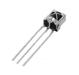
The receiver used is three terminals, commonly used in television sets!

See the figure below:

{ Read More }


Wednesday, July 10, 2013

IR Remote Control Extender Mark 3

This Mark3 version of the Infra Red extender is a special version designed to control appliances that use high frequency modulated IR remote controls.


Notes:
IR appliances use pulses (control signals) sent over a modulated IR carrier wave. The carrier wave may be modulated at various frequencies, 36-38KHz being the most popular.Some Satellite receivers use even higher frequencies than this. The IR1 remote module receives an infra red signal and separates control pulses from the modulation. To re-transmit, a 555 timer is configured as an astable oscillator. The 555 timer is controlled by the signal on the reset pin, high generating a carrier and low no carrier. Each control pulse turns on the oscillator for the duration of a logic high signal and off for a logic 0 signal, thereby creating a newly modulated IR signal. The IR module, part number IR1 is available from Harrison Electronics in the UK, IR1 may not be listed in their catalogue but if you ask for an IR1, they will send you the correct part. The IR1 arrives in a small aluminium case, the connections viewed from underneath are shown below:

Infra Red Module, IR1 Pinout

Harrison Electronics have limited supplies of the IR1 but as a replcement a standard IR module like the TSOP1838 may be used. The pinout is shown below:


The carrier frequency is determined by R1 and C3, values shown work at 39.7 kHz, but these may be altered to provide different carrier frequencies. The final CMOS 4049 invertor ensures that under "no signal" conditions both LEDs are also off.

Parts List:

C1 100u 10V
C2 100n polyester
C3 120p silver mica
C4 100n polyester
R1 150k
R2 2k2k
R3 1k
R4 47R 1W
Q1 BC109C
IC1 LM7805
IC2 555
IC3 IR1 module from Harrison Electronics or TSOP1838
IC4 4049 CMOS Invertor LED1 Red LED (or any visible colour)
LED2 TIL38 or part YH70M from Maplin Electronics


PCB Layout (courtesy of Claudio from Italy):
First the component side of the board is shown below.


And now thw pcb itself.

The Mark 3 circuit is an improvement over the Mark 1 and 2 circuits, however the drive from Q1 inverts the polarity of the output pulse. In some cases this can cause problems so the output stage is rewired as an emitter follower. This is the basis for the Mark 4 circuit. If you still have problems then I would recommend trying the Mark 4 circuit.

{ Read More }


IconIconIconFollow Me on Pinterest