​
Showing posts with label and. Show all posts

Friday, July 12, 2013

Subwoofer Filter and Low Pass Filter with LM741

The acoustics of converting a filter, there are many aspects of the economic viability of the more famous are baxandal filter low and high frequency filters and crossover Acoustic space is transformed into sub-domains, so that the Thursday Speakers. Applications, we offer a filter, the limits of the region to transform acoustic (20-20000Hz) in the region of 20-100Hz.

Subwoofer Filter and Low Pass Filter Circuit Diagram


The signal for a first high pass filter C1, C2, P1, which is undesirable level DC input. A lowpass filter consisting of R3, R4, C3 prevents frequencies above 10 kHz, which do not benefit from this design, and it would be that the instability and noise. The summary amp invert signal.

The low Summary of the amplifier signals go to a second low-pass filter to prevent the frequency from the speakers. I decided, a second order, as this box with a closed place feature. If you have a circuit with a valve system, and then simply close the Wind (Roll a pair of socks and pick at the port / Wind), this will give you a sealed box instead.
{ Read More }


Control Switch for Fan and Air Conditioner

An electronic switch that can be used to switch on both the air-conditioner as well as fan of your room, one by one. The circuit consists of power supply and control sections. The power supply section is built around transformer X1, bridge rectifier BR1 and filter capacitor C1. The 50Hz, 230V AC mains is stepped down by transformer X1 to deliver a secondary output of 9V, 300 mA. The transformer output is rectified by the bridge rectifier and filtered by capacitor C1.


When the mains is switched on for the first time, pin 3 of IC CD4017 (IC1) goes high and relay RL1 energies to switch on the fan. When mains is briefly switched off using S1 and then switched on, the power to IC1 is maintained by the charge on capacitor C1. At the same time, there is a trigger pulse on the clock input (pin 14) of IC1, which advances the decade counter and relay RL2 energies to switch-on the air-conditioner. Both the air-conditioner and the fan will be turned off if the switch is in the ‘off’ position.

Assemble the circuit on a general-purpose PCB and enclose in a suitable case. Fix the unit onto the switchboard. Use relays RL1 and RL2 with proper contact ratings. The current rating depends on the load that you are going to control.
{ Read More }


Sunday, July 7, 2013

5 Band Graphic Equaliser circuit with LA3600 and PCB

General Description
Graphic equalisers are a must in any good hi-fi systems! They enable you to shape the response of the system to the particular room, or in recordings to improve deficiencies of the equipment or the original recording. A good equalizer, used with skill can dramatically improve the quality of your listening pleasure.
This equalizer has five bands which cover all the audible frequencies, centred at 100, 320, 1,000, 3,500 and 10,000 Hz. The spacing between peak frequencies is two octaves which is quite adequate for most domestic applications. Frequency adjustment is 12dB/octave.
 
The circuit is for one channel and if you want to use it for STEREO you should build two, one for each channel of your system.
Technical Specifications – Characteristics
Working voltage: 6-15V DC
Frequency response: 20Hz-20KHz
Current: 60 ma
How it Works
This equaliser has five bands which cover all the audio frequencies, around 100, 320, 1,000, 3,500 and 10,000 Hz.
The circuit is for one channel and if you want to use it for STEREO you need two. The circuit consists of one LA3600 IC.
The circuit has been designed so that when the potentiometers are in the middle of their travel the signal is not affected at all. Turning a potentiometer in either direction will affect the corresponding frequency range accordingly. The maximum output voltage without distortion is 1 Vpp. The equaliser operates from a 12 VDC power supply which makes it suitable for use in home or car.
Construction
This work is not very difficult and if you stick to a few rules you should have no problems. The soldering iron that you use must be light and its power should not exceed the 25 Watts. The tip should be fine and must be kept clean at all times. For this purpose come very handy specially made sponges that are kept wet and from time to time you can wipe the hot tip on them to remove all the residues that tend to accumulate on it. The construction of the equaliser is very easy if you follow the diagrams and our advice carefully. The only really sensitive component are the IC. Start building the circuit by soldering the pins and the IC sockets in their places on the p.c. board. Solder then the resistors, the capacitors, making sure that the electrolytic are inserted the right way round before soldering them, and finally the potentiometers.
 
 Depending on the size and the shape of the case you are going to use for the project you can either solder the potentiometers on the p.c. board directly or use short pieces of shielded audio cable to connect them with the rest of the circuit. When you have finished soldering the components on the board check everything for possible mistakes, clean the board with a solvent to remove all traces of soldering flux and insert the IC’s in their sockets. Make sure that you align them properly and that you do not bend their pins during insertion. Make then the following connections using shielded cable for the input and output and preferably twisted twin cable for the power supply.
- The supply (6-15 VDC recommend 12volt DC) must be connected at points 1 (+) and 2 (-) of the board.
- The input is at points 5 (signal) and 4 (earth).
- The output is at points 3 (signal) and 4 (earth).
If you turn the power on, and the potentiometers of the equaliser are in their middle position there shouldn’t be any notice able difference to the music if the equaliser is inserted or not in the signal path. However turning the potentiometers should produce a noticeable effect to the reproduction.


Parts
C1 = 2.2mF 22v
C2 = 47nF
C3 = 680nF
C4 = 15nF
C5 = 220nF
C6 = 4.7nF
C7 = 68nF
C8 = 1.2nF
C9 = 22nF
C10 = 470pF
C11 = 6.8nF
C12 = 1nF
C13 = 2.2mF
C14 = 100mF 22v
C15 = 100mF 22v
R1 = 4.7k
R2 = 10k
R3, 4, 5, 6, 7 = 100k Potentiometers
IC = LA3600 link
 
{ Read More }


Thursday, July 4, 2013

Use LA1800 Portable AM and FM Radio

This portable AM and FM radio circuit is designed using the LA1800 IC and some other external components. As you can see in this circuit diagram the LA1800 manufactured by Sanyo Semiconductors , require few additional components. The LA1800 am FM portable radio circuit needs to be powered from a 3 volt DC power supply circuit.


You can use an 3 volt battery. This radio receiver circuit has a low current dissipation of 5.6mA for FM band and 3.2mA for AM band .Also the output signal is driven into earphone speakers , but you can use an additional speaker ( in that case you need to connect an additional small power audio amplifier).
{ Read More }


Friday, May 17, 2013

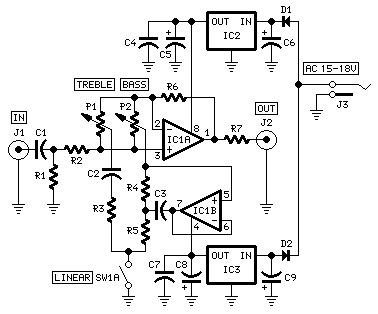
Preamplifier Bass and Treble Controls

Preamplifier Bass and Treble Controls

Need a tone control, this module can be inserted into the chain between the Control Center and power amplifier. The circuit is based on an original design by Reg Williamson, published in Electronics World + Wireless World, circuit ideas, January 1991.

The tone control circuit will take the form of any of the traditional low treble adjustment, or the type of shelves, which is similar to a "tilt" control, but with separate bass and treble. Asymptotic slopes for both are about 4dB/octave, but begin to level off at 100 Hz and 10 kHz, with a maximum of ± 15 dB at the ends of the audio band.

Component values ​​in parentheses are the shelving of control. In this case, the platform starts around 250 Hz and 4 kHz, flatten to a maximum of ± 6dB an octave above or below the central point is 1 kHz. Reactive elements for low-end includes a generalized impedance converter, which simulates an inductor in series with a resistor (spinner).

When set to the centers of their respective electrical controls, equalizers reactive elements are almost out of circuit. With these settings, the circuit behaves as a unity gain amplifier with 100% negative votes. Still, the reactive elements can be changed completely with a DPST on / off.

As with the other modules in this series, each electronic card can be fitted in a standard: Hammond extruded aluminum cases are well suited to accommodate the tables in this preamp. In particular, instances of size 16 x 10.3 x 5.3 cm or 22 x 10.3 x 5.3 cm look very good when stacked. See below an example of the possible arrangement of the front and back of this module.
{ Read More }


12V Low side and High side PWM Motor Light Controller

12V Low side and High side PWM Motor/Light Controller12V Low side PWM Motor/Light Controller
12V Low side and High side PWM Motor/Light Controller12V High side PWM Motor/Light Controller

These two schematics are variations on addition PWM circuit that I designed. The diagrams are for 12V operation alone and there are aerial ancillary (common ground) and low ancillary (common +12V) versions. The low ancillary adaptation of the ambit uses an N Channel FET, the aerial ancillary adaptation of the circuit uses a P Channel FET. N Channel accessories tend to handle added accepted than P Channel devices, they are additionally beneath expensive. The aerial ancillary adaptation of the ambit is advantageous back one ancillary of the bulk has to be grounded.

This Circuit can about-face a adequately aerial bulk of current, an IRFZ34N MOSFET can handle over 35 Amps if affiliated to a able calefaction sink. Higher ability FETs, such as the IRFZ48N or IRF1010Z can be commissioned if alike beyond currents are required. It is additionally accessible to affix assorted FETs in alongside for alike added accepted capacity. Always use thermally conductive grease amid the FET and the calefaction sink, and bethink that the calefaction bore is electrically live.

Inductive endless (motors) may crave appropriate affliction back they can accomplish ample voltage spikes that can accident the MOSFET. Replacing the 1N4002 with a fast accretion diode may advice blot the about-face voltage bang back active an anterior bulk such as a motor. If you use these circuits for abstracts with electric vehicles, be abiding to install a ambit breaker in alternation with the battery, the ambit breaker should be accessible to ability by the driver. This is abnormally important due to the actuality that back MOSFETs fail, they generally abbreviate out, abrogation the motor on at abounding speed.

Note that the pwm ascendancy has an adverse aftereffect on these two circuits, the low ancillary adaptation is on with a aerial pin 7 achievement voltage and the aerial ancillary adaptation is on with a low output.

The inductor on the aboideau ancillary of the ability MOSFET transistor can be a ferrite bean or a few turns of wire captivated about a 10 ohm, 1/4W resistor. The purpose of this allotment is to anticipate RF oscillations from occurring in the MOSFET circuitry.

{ Read More }


Tuesday, April 2, 2013

Temperature and Humidity Sensor

Temperature and humidity
Temperature and humidity sensors used are SHT75. This sensor is a chip that can measure temperature and humidity as well. The use of these sensors with consideration of its small size and reliability. The output of this sensor has the form of digital data in the chip because it has been there for a 14bit ADC.


Temperature measurement range between -40-123,8 º C and humidity between 0-100% Rh. Measurement accuracy reaches ± 0.3 per increase of 25 º C for temperature and ± 1.8% RH for humidity.
Temperature and humidity sensor

The default measurement resolution of this sensor is 14 bits to 12 bits and temperature sensors for humidity sensors, can also use only 12 bit resolution and 8 bits.
{ Read More }


IconIconIconFollow Me on Pinterest