Showing posts with label battery. Show all posts

Wednesday, August 7, 2013

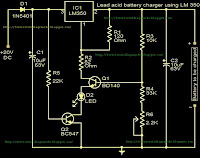
Battery charger using LM350

This is very useful circuit for the vehicle owners.Because most of time they have to bring their heavy 12v battery hear and there.now you dont want to do that.because you can build your own 12v charger


Notes

Use a 20 to 30 V / 3A DC power supply for powering the circuit.
This circuit is not possible for charging GEL type batteries as it draw large amounts of current.
{ Read More }


Wednesday, July 10, 2013

Li Ion Polymer Battery Charger Using LTC4098

Using the LTC4098 USB Power-Path controller you can design an high efficiency , full-featured Li-Ion Polymer battery charger using few external electronic components . This Li-Ion Polymer battery charger circuit can be used with many power distribution sources like: USB, wall adapter, automotive, Firewire or other high voltage DC/DC converters, and a Li-Ion/Polymer battery.

Li-Ion Polymer Battery Charger Circuit diagram


For automotive and other high voltage applications, the LTC4098 interface with a Linear Technology external switching regulator to provide a high efficiency high voltage power path. An overvoltage circuit protects the LTC4098 from high voltage damage on the USB/wall adaptor inputs with an N-channel FET and an resistor .

The voltage on the pin7 (Prog) pin always represents the actual charge current by using the following formula: IBAT =(VPROG/RPROG)x1030 The charge current is programmed using a single resistor from PROG to ground.The program resistor and the charge current are calculated using the following equations :RPROG =1030V/ICHG ; ICHG =1030V/RPROG . The charge voltage will be 4.2V with 0.5 accuracy . As you can see in the schematic circuit this charger is very simple an you need to apply just few easy equations to design a high efficiency Li-Ion Polymer charger .
{ Read More }


Tuesday, July 9, 2013

Solar Powered SLA Battery Maintenance

This circuit was designed to ‘baby-sit’ SLA (sealed lead-acid or ‘gel’) batteries using freely available solar power. SLA batteries suffer from relatively high internal energy loss which is not normally a problem until you go on holidays and disconnect them from their trickle current charger. In some cases, the absence of trickle charging current may cause SLA batteries to go completely flat within a few weeks. The circuit shown here is intended to prevent this from happening. Two 3-volt solar panels, each shunted by a diode to bypass them when no electricity is generated, power a MAX762 step-up voltage converter IC. 

Circuit diagram:
Solar Powered SLA Battery-Maintenance-Circuit-Diagram
Solar Powered SLA Battery Maintenance Circuit Diagram

The ‘762 is the 15-volt-out version of the perhaps more familiar MAX761 (12 V out) and is used here to boost 6 V to 15 V.C1 and C2 are decoupling capacitors that suppress high and low frequency spurious components produced by the switch-mode regulator IC. Using Schottky diode D3, energy is stored in inductor L1 in the form of a magnetic field. When pin 7 of IC1 is open-circuited by the internal switching signal, the stored energy is diverted to the 15-volt output of the circuit. The V+ (sense) input of the MAX762, pin 8, is used to maintain the output voltage at 15 V. C4 and C5 serve to keep the ripple on the output voltage as small as possible. R1, LED D4 and pushbutton S1 allow you to check the presence of the 15-V output voltage.

D5 and D6 reduce the 15-volts to about 13.6 V which is a frequently quoted nominal standby trickle charging voltage for SLA batteries. This corresponds well with the IC’s maximum, internally limited, output current of about 120 mA. The value of inductor L1 is not critical — 22 µH or 47 µH will also work fine. The coil has to be rated at 1 A though in view of the peak current through it. The switching frequency is about 300 kHz. A suggestion for a practical coil is type M from the WEPD series supplied by Würth (www.we-online.com). Remarkably, Würth supply one-off inductors to individual customers. At the time of writing, it was possible, under certain conditions, to obtain samples, or order small quantities, of the MAX762 IC through the Maxim website at www.maxim-ic.com.
 
 
Streampowers
{ Read More }


Battery Switch With Low Dropout Regulator

In the form of the LT1579 Linear Technology (www.linear-tech.com) has produced a practical battery switch with an integrated low-dropout regulator. In contrast to previous devices no diodes are required. The circuit is available in a 3.3 V version (LT1579CS8-3.3) and in a 5 V version (LT1579CS8-5), both in SO8 SMD packages. There is also an adjustable version and versions in an SO16 package which offer a greater range of control and drive signals. The main battery, whose terminal voltage must be at least 0.4 V higher than the desired output voltage, is connected to pin IN1. The backup battery is connected to pin IN2. The regulated output OUT can deliver a current of up to 300 mA. The LDO regulator part of the IC includes a pass transistor for the main input voltage IN1 and another for the backup battery on IN2.

Battery_Switch_With_LDO_Regulator_Circuit_Diagramw

The IC will switch over to the backup battery when it detects that the pass transistor for the main voltage input is in danger of no longer being able to maintain the required output voltage. The device then smoothly switches over to the backup battery. The open-drain status output BACKUP goes low to indicate when this has occurred. When neither battery is able to maintain the output voltage at the desired level the open-drain output DROPOUT goes low. The LT1579 can operate with input voltages of up to +20 V from the batteries. The regulator output OUT is short-circuit proof. The shutdown input switches off the output; if this feature is not required, the input can simply be left open.
 
 
Streampowers
{ Read More }


12V Powered 12V Lead Acid Battery Charger with Indicator

Some of you might wonder why a charger is needed at all, to charge a 12 Volt battery from a 12 Volt source! Well, firstly the "12 Volt" source will typically vary anywhere from 11 Volt to 15 Volt, and then a battery needs a controlled charge current and voltage, which cannot result from connecting it directly to a voltage source. The charger described here is intended for charging small 12 Volt lead acid batteries, such as the gelled or AGM batteries of capacities between about 2 and 10 Ah, using a cars electrical system as power source, regardless of whether the car engine is running or not. I built this charger many years ago, I think I was still in school back then. On request of a reader of my web site, Im publishing it now, despite being a rather crude circuit.

12V Powered 12V Lead Acid Battery Charger with Indicator
It works, it is uncritical to build, and uses only easy-to-find parts, so it has something in its favor. The downside is mainly the low efficiency: This charger wastes about as much power as it puts into the battery. The charger consists of two stages: The first is a capacitive voltage doubler, which uses a 555 timer IC driving a pair of transistors connected as emitter followers, which in turn drive the voltage doubler proper. The doubler has power resistors built in, which limit the charging current. The second stage is a voltage regulator, using a 7815 regulator IC. Its output is applied to the battery via a diode, which prevents reverse current and also lowers the voltage a bit.

12V Powered 12V Lead Acid Battery Charger with Indicator
The resulting charge voltage is about 14.4V, which is fine for charging a gelled or AGM battery to full charge, but is too high as a trickle charger, so dont leave this charger permanently connected to a battery. If you would like to do just that, then add a second diode in series with D3! There is a LED connected as a charge indicator. It will light when the charge current is higher than about 150mA. The maximum charge current will be roughly 400mA. There is an auxiliary output, that provides about 20V at no load (depending on input voltage), and comes down as the load increases. I included this for charging 12V, 4Ah NiCd packs, which require just a limited current but not a limited voltage for charging.

12V Powered 12V Lead Acid Battery Charger with Indicator
Note that if the charge output is short-circuited, the overcurrent protection of U2 will kick in, but the current is still high enough to damage the diodes, if it lasts. So, dont short the output! If instead you short the auxiliary output, the fuse should blow. I built this charger into a little homemade aluminum sheet enclosure, using dead-bug construction style. Not very tidy, but it works. Note the long leads on the power resistors. They are necessary, because with shorter leads the resistors will unsolder themselves, as they get pretty hot! The transistors and the regulator IC are bolted to the case, which serves as heat sink. The transistors dont heat up very much, but the IC does.


Source by Streampowers
{ Read More }


Monday, July 8, 2013

Designing A Li Ion Battery Charger with Load Sharing MCP73837


Batteries often serve as the main energy source for portable electronic devices. Although they depend on batteries, portable consumer electronic products, such as GPS devices and multi-media players, often consume energy directly from an ac-dc wall adapter or accessory power adapter (or “Auto Adapter”) when the battery is low or the device is in a stationary mode. Due to their cost effectiveness over their useful life, rechargeable batteries are often used for the power source of the portable electronic device.

Attributes such as “relatively high energy density” and “maintenance free” make Lithium-Ion (Li-Ion) batteries popular in the portable consumer electronic products. Refer to the application note, AN1088, “Selecting the Right Battery System For cost Sensitive Portable Applications While maintaining Excellent Quality” (DS01088) for characteristics of Li-Ion batteries. Some examples of how to properly design with Li-Ion batteries will be discussed in this application note. [Link] 
{ Read More }


Wednesday, June 12, 2013

Singular Cell Phone Can Be Used Battery 5 Exactly Like the Flashlight Without Screen

Japanese PHS operator Willcom shows the battery No. 5 mobile phone use

                                     Shaped like a remote control or torch


 Japanese PHS operator Willcom and Sanyo Electric has unveiled a battery of PHS mobile phone use. The phone has no screen, the body covered with digital dial key, shaped like a remote control or a flashlight, using a Sanyo eneloop 5 batteries.

Sanyo rechargeable battery technology has advanced, eneloop nickel-metal hydride batteries for its launch, significantly improved the "self-discharge" and other undesirable characteristics, one year after the electricity can still maintain a 80% claims to have up to five times more than ordinary battery working time and can be recharged 1000 times. Sanyo eneloop batteries have been launched based on a lot of electronic gadgets.

Willcoms mobile phone was cylindrical, 42 mm in diameter, length 134 mm, the upper part of the SIM card can be loaded for specific Willcom W-SIM. Use an eneloop battery can be sure that the phone five hours of talk time and 250 hours of standby time. At present mobile phone is still in prototype stage show.

3G mobile phone shipments in the Japanese market more than 98% and the remaining share was for the 2G mobile phones and
PHS are divided. Willcom continues to continue to bring new phones to market.

Using a Sanyo eneloop batteries, SIM cards can be put into the upper

At present mobile phone is still in prototype stage show
{ Read More }


Tuesday, May 28, 2013

Solar battery charger

This is solar battery charger with over charge protection.This circuit depends on IC LM723.Some times some batteries destroy because of charging over the limit.But this circuit contains an over charge protection unite.


{ Read More }


Sunday, April 21, 2013

Battery Equality Monitor

Almost all 24V power systems in trucks, 4WDs, RVs, boats, etc, employ two series-connected 12V lead-acid batteries. The charging system can only maintain the sum of the individual battery voltages. If one battery is failing, this circuit will light a LED. Hence impending battery problems can be forecast. The circuit works by detecting a voltage difference between the two series connected 12V batteries. Idle current is low enough to allow the unit to be permanently left across the batteries.
Circuit diagram:
battery_equality_monitor_schematic_circuit_diagramw
Parts:
R1 = 2.K
R2 = 4.7K
R3 = 39K
R4 = 39K
R5 = 1.5K
R6 = 1.5K
Q1 = BC547
Q2 = BC547
Q3 = BC557
D1 = 3mm Red LED
D2 = 3mm GreenLED
B1 = DC 12 Volt
B2 = DC 12 Volt


{ Read More }


Friday, April 12, 2013

Lead Acid Battery Protector

The circuit described right here can be used to  ensure  that  a  12 V  sealed  lead  acid  (SLA)  gel battery isn’t discharged too deeply. The  predominant part of the circuit is a bistable relay,  which is pushed by using the output of an op amp. 

Circuit diagram :

Lead Acid Battery Protector Circuit Diagram
The battery voltage is first diminished by way of D1, R1,  P1 and R2, and then repeatedly compared  with a reference voltage set up with the support of diode D2.  When the battery discharges too much and  its terminal voltage drops beneath the level  set by using P1, the output of the opamp becomes  High, which causes the relay to toggle. This  in turn isolates the weight from the battery. The  battery will additionally be reconnected by manner of S1 once the  battery has been changed or recharged. 

The relay used in the prototype is a 5 V bistable type made through Omron (G6AK-234P-ST-US  5 VDC). The two windings of the relay each  have a resistance of 139 Ω (for the RAL-D 5  W-K made with the aid of Fujitsu that is 167 Ω). When the  battery voltage starts to develop into too low and  the relay is being reset the present consumption of the circuit is ready 45 mA. Shortly  after the burden has been disconnected, when the battery voltage upward throughsts above the reference  voltage once more, the reset coil will no longer be  powered and the current consumption drops  back to about 2.5 mA. 

The vary of P1 has deliberately been kept  small. With a reference voltage of 5.6 V (D2)  and a voltage drop of 0.64 V throughout D1, the circuit reacts within a voltage span of eleven.5 V and  11.8 V. This vary is clearly depending on the zener diode used and the tolerance. 

For a larger span you can use a larger value  for P1 without any problems. With the potentiometer at its mid setting the circuit switches  at about 11.6 V.
 
 
Author : Jürgen Stannieder
{ Read More }


IconIconIconFollow Me on Pinterest