Showing posts with label charger. Show all posts

Wednesday, August 7, 2013

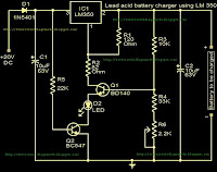
Battery charger using LM350

This is very useful circuit for the vehicle owners.Because most of time they have to bring their heavy 12v battery hear and there.now you dont want to do that.because you can build your own 12v charger


Notes

Use a 20 to 30 V / 3A DC power supply for powering the circuit.
This circuit is not possible for charging GEL type batteries as it draw large amounts of current.
{ Read More }


Thursday, July 11, 2013

12V 4 AA Cell Differential Temperature Charger

This project includes a number of improvements over my older Temperature Controlled NICD Charger circuit. This circuit runs on 12VDC, allowing it to be used in a car or from a 12V solar power system. Additionally, a current sensor LED verifies that the cells are receiving charging current. Note that the current sensor circuitry is not shown in the circuit board photo above, it was added to the side of the main board via a small perfboard.

12V, 4-AA Cell Differential Temperature Charger Circuit diagram

12V, 4-AA Cell Differential Temperature Charger

The current is adjustable in three steps from 100 to 300mA, allowing fast charging of AA, AAA or other small cells. Battery packs from 1 to 6 cells can be charged with this circuit. NiMH and older NiCD cells are supported. The circuit is protected from reverse input voltage and reversed cells.

Connections:
  • 12VDC (nominal) power input
  • Connections for the Battery Under Charge
Controls:
  • Power On/Off switch
  • Charge Start switch
  • 3 step Charge Current Select jumper
  • Calibrate/[Latch] mode jumper
  • Temperature sensor calibrate trimmer
  • Red/Green Charging/Done light
  • Amber Current Flow light
Theory:
12VDC power is supplied to the circuit from an external source such as a car battery system, a 12V solar power system or a regulated "wall wart" supply. If DC power is applied backwards, the 6A05 crowbar diode causes the 3A fuse to blow, protecting the circuit from reverse voltage. The power switch routes power to the 78L09 voltage regulator and the battery. The 78L09 regulator provides regulated power to the rest of the circuit.

The battery current loop starts with the +12V supply, then runs through the battery and through a 1N5819 reverse voltage protection diode. Current continues through the LM317 1 amp adjustable voltage regulator which is wired as a constant current source, through the IRFD110 power MOSFET transistor, which switches charging current on and off, through the 0.1 ohm current sensing resistor to ground (12VDC negative). The charge current is selected by jumpering one of three current-set resistors on the negative side of the LM317 regulator. The 120 ohm trickle charge resistor always allows 10mA of current to flow through the battery.

The temperature control part of the circuit starts with a matched pair of 10K NTC thermistors. One thermistor is epoxied to a small metal reference temperature plate. The other thermistor is epoxied to a metal battery holder. The temperature sensors are balanced by the calibrate potentiometer. The 100nF and 50nF capacitors across the thermistors cause different start-up time delays to insure that the following circuitry powers up in the off state.

The upper half of the TLC2272CP rail-to-rail op-amp is wired as a latching comparator when the Cal/Latch jumper is present (operate mode), the circuit becomes a regular comparator with hysteresis when the jumper is off (calibrate mode). Assuming the battery is cold and the circuit is in operate mode, the start switch turns the op-amp on for a charging cycle. When the battery temperature exceeds the reference temperature, the op-amp turns off and the diode in the feedback loop latches the op-amp off. The op-amp output also drives the IRFD110 current switch MOSFET.

The lower half of the TLC2272CP simply inverts the output from the upper part of the op-amp, this gives a bipolar drive signal for running the Red/Green Charging/Done light.

An optional current flow lamp was added to the circuit. Rechargeable batteries tend to get corroded contacts which can prevent the charging current from flowing. The lamp provides an indication that the charging current is really making its way through the batteries. The current Flow lamp circuit consists of an LM358 op-amp wired as a current measurement amplifier that monitors the voltage drop across a 0.1 ohm resistor. The LM358 is specially suited for this type of circuit. The output of the first LM358 stage is further boosted and offset by the second LM358 stage. This produces a digital signal that drives the indicator LED through a current limiting resistor. If you dont want to add the Current Flow circuit, replace the 0.1 ohm resistor with a wire jumper.

Construction:
The circuit was built on a custom home-built circuit board, a hand-wired perf board would also make a good platform for this project. The LM317 regulator is mounted on an aluminum heat sink under the main board, the heat sink should be kept away from the two temperature sensors. The reference temperature sensor is mounted to a small piece of aluminum that is thermally isolated from the battery holder and the rest of the circuitry. All of the sub-components are mounted on a piece of plexiglass or another non conducting material.

Calibration:
Put the circuit in one location and allow the temperature to stabilize for an hour or so. Remove the Cal/[Latch] jumper. Adjust the 20 turn Calibrate trimmer a little bit past the point where the Charge/Done light turns red. Put the Cal/[Latch] jumper back.

Use:
The charger should only be used in a cool location with a fairly constant temperature. Install the batteries to charge in the battery holder, start with the negative side of the socket and connect the alligator clip to the + side of the last cell. Put a piece of insulating foam over the battery holder to keep the warmth in the battery. If the battery is already hot, allow it to cool down before starting the charge cycle. The Charging/Done light should now be green.

Push the Start switch and the Charging/Done light should turn red. The Current Flow light should turn on, if it doesnt, try reseating the cells in the holder. After some amount of charging, the battery will warm up, the Charging/Done light will turn green and the battery charge cycle be finished. If you want to equalize the weaker cells in the battery, allow the pack to cool down then run another charging cycle, the second time should not take very long.
{ Read More }


Wednesday, July 10, 2013

Li Ion Polymer Battery Charger Using LTC4098

Using the LTC4098 USB Power-Path controller you can design an high efficiency , full-featured Li-Ion Polymer battery charger using few external electronic components . This Li-Ion Polymer battery charger circuit can be used with many power distribution sources like: USB, wall adapter, automotive, Firewire or other high voltage DC/DC converters, and a Li-Ion/Polymer battery.

Li-Ion Polymer Battery Charger Circuit diagram


For automotive and other high voltage applications, the LTC4098 interface with a Linear Technology external switching regulator to provide a high efficiency high voltage power path. An overvoltage circuit protects the LTC4098 from high voltage damage on the USB/wall adaptor inputs with an N-channel FET and an resistor .

The voltage on the pin7 (Prog) pin always represents the actual charge current by using the following formula: IBAT =(VPROG/RPROG)x1030 The charge current is programmed using a single resistor from PROG to ground.The program resistor and the charge current are calculated using the following equations :RPROG =1030V/ICHG ; ICHG =1030V/RPROG . The charge voltage will be 4.2V with 0.5 accuracy . As you can see in the schematic circuit this charger is very simple an you need to apply just few easy equations to design a high efficiency Li-Ion Polymer charger .
{ Read More }


Tuesday, July 9, 2013

12V Powered 12V Lead Acid Battery Charger with Indicator

Some of you might wonder why a charger is needed at all, to charge a 12 Volt battery from a 12 Volt source! Well, firstly the "12 Volt" source will typically vary anywhere from 11 Volt to 15 Volt, and then a battery needs a controlled charge current and voltage, which cannot result from connecting it directly to a voltage source. The charger described here is intended for charging small 12 Volt lead acid batteries, such as the gelled or AGM batteries of capacities between about 2 and 10 Ah, using a cars electrical system as power source, regardless of whether the car engine is running or not. I built this charger many years ago, I think I was still in school back then. On request of a reader of my web site, Im publishing it now, despite being a rather crude circuit.

12V Powered 12V Lead Acid Battery Charger with Indicator
It works, it is uncritical to build, and uses only easy-to-find parts, so it has something in its favor. The downside is mainly the low efficiency: This charger wastes about as much power as it puts into the battery. The charger consists of two stages: The first is a capacitive voltage doubler, which uses a 555 timer IC driving a pair of transistors connected as emitter followers, which in turn drive the voltage doubler proper. The doubler has power resistors built in, which limit the charging current. The second stage is a voltage regulator, using a 7815 regulator IC. Its output is applied to the battery via a diode, which prevents reverse current and also lowers the voltage a bit.

12V Powered 12V Lead Acid Battery Charger with Indicator
The resulting charge voltage is about 14.4V, which is fine for charging a gelled or AGM battery to full charge, but is too high as a trickle charger, so dont leave this charger permanently connected to a battery. If you would like to do just that, then add a second diode in series with D3! There is a LED connected as a charge indicator. It will light when the charge current is higher than about 150mA. The maximum charge current will be roughly 400mA. There is an auxiliary output, that provides about 20V at no load (depending on input voltage), and comes down as the load increases. I included this for charging 12V, 4Ah NiCd packs, which require just a limited current but not a limited voltage for charging.

12V Powered 12V Lead Acid Battery Charger with Indicator
Note that if the charge output is short-circuited, the overcurrent protection of U2 will kick in, but the current is still high enough to damage the diodes, if it lasts. So, dont short the output! If instead you short the auxiliary output, the fuse should blow. I built this charger into a little homemade aluminum sheet enclosure, using dead-bug construction style. Not very tidy, but it works. Note the long leads on the power resistors. They are necessary, because with shorter leads the resistors will unsolder themselves, as they get pretty hot! The transistors and the regulator IC are bolted to the case, which serves as heat sink. The transistors dont heat up very much, but the IC does.


Source by Streampowers
{ Read More }


Monday, July 8, 2013

Designing A Li Ion Battery Charger with Load Sharing MCP73837


Batteries often serve as the main energy source for portable electronic devices. Although they depend on batteries, portable consumer electronic products, such as GPS devices and multi-media players, often consume energy directly from an ac-dc wall adapter or accessory power adapter (or “Auto Adapter”) when the battery is low or the device is in a stationary mode. Due to their cost effectiveness over their useful life, rechargeable batteries are often used for the power source of the portable electronic device.

Attributes such as “relatively high energy density” and “maintenance free” make Lithium-Ion (Li-Ion) batteries popular in the portable consumer electronic products. Refer to the application note, AN1088, “Selecting the Right Battery System For cost Sensitive Portable Applications While maintaining Excellent Quality” (DS01088) for characteristics of Li-Ion batteries. Some examples of how to properly design with Li-Ion batteries will be discussed in this application note. [Link] 
{ Read More }


Friday, July 5, 2013

USB Car Charger Adapter

This USB car charger adapter project is a DC DC power converter that safely converts the 12V car battery voltage into stable 5V. This USB car charger circuit can be used to supply power from a car cigar lighter socket to a portable device that require a 5 volts . This circuit makes it possible to power/recharge any USB power-operated device, using in-dash board cigar lighter socket of your car.

USB Car Charger Adapter Circuit diagram


USB Car Charger Adapter

The DC supply available from the cigar lighter socket is fed to an adjustable, three-pin regulator LM317L (IC1). R1 and R2 resistors regulate the output of IC1 to steady 5V, which is available at the ‘A’ type female USB socket. Red LED1 indicates the output status and zener diode ZD1 acts as a protector against high voltage.As you can see in the circuit diagram , the circuit is very simple and require just few common cheap components .Because this circuit not require many components , you can put all components in the cigar plug socket .
{ Read More }


Tuesday, May 28, 2013

Solar battery charger

This is solar battery charger with over charge protection.This circuit depends on IC LM723.Some times some batteries destroy because of charging over the limit.But this circuit contains an over charge protection unite.


{ Read More }


IconIconIconFollow Me on Pinterest