Showing posts with label inverter. Show all posts

Friday, December 20, 2013

12V Flourescent Lamp Inverter

Fluorescent tubes use far less energy than incandescent lamps and fluorescent tubes last a great deal longer as well. Other advantages are diffuse, glare-free lighting and low heat output. For these reasons, fluorescent lighting is the natural choice in commercial and retail buildings, workshops and factories. For battery-powered lighting, fluorescent lights are also the first choice because of their high efficiency. The main drawback with running fluorescent lights from battery power is that an inverter is required to drive the tubes.

12V Fluorescent Lamp Inverter Circuit diagram:

12-volt-flourescent-lamp-Inverter-circuit

Fig.1: two switch-mode circuits are involved here: the DC-DC inverter involving IC1, Q1 & Q2 and the fluoro tube driver which converts high voltage DC to AC via IC3 and Q3 & Q4 in a totem-pole circuit.
Inverter efficiency then becomes the major issue. There are many commercial 12V-operated fluorescent lamps available which use 15W and 20W tubes. However, it is rare to see one which drives them to full brilliance. For example, a typical commercial dual 20W fluorescent lamp operating from 12V draws 980mA or 11.8W. Ignoring losses in the fluorescent tube driver itself, it means that each tube is only supplied with 5.9W of power which is considerably less than their 20W rating. So while the lamps do use 20W tubes, the light output is well below par.

Warning:
This circuit generates in excess of 300V DC which could be lethal. Construction should only be attempted by those experimenced with mains-level voltages and safety procedures.

Source: http://www.ecircuitslab.com/2011/08/12v-flourescent-lamp-inverter.html
{ Read More }


Wednesday, July 10, 2013

DC to AC Inverter with IC CD4047

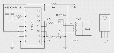
This DC to AC inverter circuit work based on unstable multi vibrator does. In this circuit, IC CD4047 is chosen as a heart of unstable multivibrator, because this IC type gives a complementary output that has opposite phase to another ( pin 10 and 11 as seen in Figure 1), and has 50 % duty cycle that satisfy to generate a pulse for inverter.

DC to AC Inverter with IC CD4047 Circuit Diagram

DC to AC Inverter Circuit Diagram

{ Read More }


Tuesday, July 9, 2013

Simple 100 Watt Inverter

This is a simplest circuit for 100 watt inverter for generating 220vAC from 12vDC. I say simplest because here in this inverter circuit a minimum number of components are used to design the schematic, which is quite difficult to make a circuit like this with further fewer components.
 
Simple 100 Watt Inverter Circuit Diagram

 Inverter Circuit Diagram

This 100W inverter circuit works great for small loads like a fan or 2-3 bulbs/lamps. In this circuit as IC1 we used a CD 4047 IC to generate 100Hz frequency (180 degree out of phase). CD 4047 IC is from Texas Instruments. It is mostly used as Astable/Monostable signal generator device. In this circuit it is triggered as astable multivibrator by the capacitor C1 between the Pin 1 and 3 of CD4047. And VR1 is used to adjust the frequency of signal.

Four 2N3055 transistors are used to amplify the pulse trains that are pre-amplified by two TIP122 transistors. There used three transistors for each side (half cycle), one TIP122 & two 2N3055 transistor to drive the output transformer (TX in circuit). Four 2N3055 transistors are used as driving transistor. An inverters maximum output power depends on two factors; one is the max current rating of transformer’s primary winding and other factor is the current rating of driver transistors.

Transformer: Use a 12v-0-12v, 10A step-down transformer in reverse. That’s mean secondary winding (12v-0-12v) will be the primary and primary winding (220VAC side) will be the secondary (output). So that it will worked like a step-up transformer. You can also use a 5A transformer instead of 10A, if you couldn’t have 10A.  But the output power will decrease to 60 Watt.

+12VDC: A good quality 12V car battery could be used for DC 12V.

Parts list :
VR1 = 250K (Variable resistor/POT)
R1, R2 = 4.7K-1/4W Resistor
R3, R4, R5, R6 = 0.1R-5W
C1 = 0.022uF
C2 = 220uF-25V
D1 = BY127 Diode
D2 = 9.1V Zener Diode
Q1, Q4 = TIP122 Transistor
Q2, Q3, Q5, Q6 = 2N3055 Transistor
F1 = 10A Fuse
IC1 = CD4047
TX = 12-0-12V, 10A Step-down Transformer

{ Read More }


Friday, April 12, 2013

Simple Mini Power Inverter

Even robot systems occasionally need a negative supply voltage for some purpose or other, and in this kind of application in particular there is a need for an effective circuit that does  not  make  greater demands  then  necessary in terms of current or space. If a low current 5 V supply is needed and only +5 V is available, a natural manufacturer to turn  to  is  Maxim,  and indeed in this case they do not let us down.The best known integrated  circuit made by this company is the MAX232, a level shifter for serial ports with an integrated charge pump that does not need an external inductor.

Simple Mini Power Inverter   image:
Mini Power Inverter Img

Along the same lines, although with a more stable output voltage and higher efficiency, is the MAX660. The device can ‘mirror’ any input voltage between 1.5 V and 5.5 V. With a 5 V input the output is typically –4.7 V with a load of 100 mA. Efficiency at 10 mA is around 96 % and at 100 mA is around 88 %. With an open-circuit output the IC draws a quiescent current of just 120 μA.There is little to say about the circuit itself.

Simple Mini Power Inverter Circuit diagram:
Simple Mini Power Inverter Circuit Diagram

The 0 Ω resistor on pin 1 selects the operating frequency. With R1 fitted, the circuit operates at 80 kHz; without it, at 10 kHz. The combination of L1 and C5 slightly reduces ripple on the output voltage; the choice of inductor is not as critical as it would be if it formed part of the switching circuit.Gerber files for the printed circuit board (which uses some SMD components) are available for download from the Elektor website, ref. 070279-11.zip. R1, C1 and C4 are 0603 SMDs and C3 is an SMD tantalum electrolytic capacitor. Either the MAX-660CSA or the MAX660M can be used; both come in SO8 packages. L1 is a 10 μH SMD inductor rated at 300 mA.

Source: http://www.ecircuitslab.com/2011/11/even-robot-systems-occasionally-need.html 

{ Read More }


IconIconIconFollow Me on Pinterest