Wednesday, June 12, 2013

Motorcycle Alarm Circuit

Circuit Notes

Any number of normally open switches may be used. Fit the mercury switches so that they close when the steering is moved or when the bike is lifted off its side-stand or pushed forward off its centre-stand. Use micro-switches to protect removable panels and the lids of panniers etc. While at least one switch remains closed, the siren will sound. About two minutes after the switches have been opened again, the alarm will reset. How long it takes to switch off depends on the characteristics of the actual components used. But, up to a point, you can adjust the time to suit your requirements by changing the value of C1.

The circuit board and switches must be protected from the elements. Dampness or condensation will cause malfunction. Without its terminal blocks, the board is small. Ideally, you should try to find a siren with enough spare space inside to accommodate it. Fit a 1-amp in-line fuse close to the power source. This protects the wiring. Instead of using a key-switch you can use a hidden switch; or you could use the normally closed contacts of a small relay. Wire the relay coil so that it is energized while the ignition is on. Then every time you turn the ignition off, the alarm will set itself.

When its not sounding, the circuit uses virtually no current. This should make it useful in other circumstances. For example, powered by dry batteries and with the relay and siren voltages to suit, it could be fitted inside a computer or anything else thats in danger of being picked up and carried away. The low standby current and automatic reset means that for this sort of application an external on/off switch may not be necessary. Electronics Circuit Application
{ Read More }


100W Quad Car Amplifier circuits

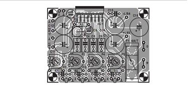
This quad final amplifier is actually intended to be used in a car, but it can naturally also be used for a variety of other medium-power applications. The TDA7375A can be successfully used in all situations in which a reasonable amount of audio power is desired and only a relatively low supply voltage is available. This IC is the successor to the TDA7374B, which forms the heart of the active loudspeaker system described earlier this year. Such a quad IC amplifier is naturally an excellent choice for this application, especially since the individual amplifiers can be connected in pairs in the bridge configuration, which allows them to provide approximately four times as much power.


 In addition, all inputs have RC networks (R1/C1, etc.) to block possible RF interference. The function of R6 is to separate the grounds of the input and output stages, in order to avoid possible ground loops that might arise with the use of multiple modules. A 5-W type is used for this resistor, in order to prevent it from going up in smoke if the ground connection of the power supply comes loose. C10 decouples the internal voltage divider, which biases the internal amplifier stages to half of the supply voltage. RC network R5/C9 provides a delayed, plop-free switch-on.


 C15 and C16 are local bypass capacitors for the supply voltage. The power supply ripple rejection of the TDA7375A is approximately 50 dB. If you want to use only a transformer, bridge rectifier and smoothing capacitor for the power supply, the minimum requirement is a transformer rated at 12 V / 30 VA in combination with a 10,000-µF electrolytic capacitor (remember that the maximum allowable supply voltage is 18 V). One of the few drawbacks of this quad amplifier is that two of the channels are inverted with respect to the other two. For this reason, the polarity of each loudspeaker terminal is marked on the circuit board layout (e.g., +LS1 and –LS4) to indicate which terminal of the loudspeaker should be connected where.


Radial electrolytic capacitors rated at 3300µF/16V and having a diameter of only 12 mm are used for the output capacitors, which allows the circuit board to remain relatively compact. Our preferred type of electrolytic capacitor is a member of the Rubycon ZL series, which can handle no less than 3.4 A of ripple current. The maximum current consumption of the circuit with all four channels driven to the clipping level (with 4-Ω loads) is approximately 2.1 A. The TDA7375A can also be used with 2-Ω loads. However, in this case the internal temperature rises considerably, since the Multiwatt 15V package has a rather large thermal impedance of 1.8 ºC/W.
In the interest of the service life of the IC, it is thus a good idea to use a somewhat larger heat sink. A 4 A/T fuse has been selected in consideration of possible 2-Ω operation. If you limit the load to 4 Ω, the fuse value can be reduced to 2 A/T. The output terminals of the amplifiers can be found on the circuit board next to the associated electrolytic capacitors. The related ground connections for LS1 and LS2 are located next to the LS1 and LS2 terminals, but the ground connections for LS3 and LS4 are located on the left, next to the IC, since this gives the best current paths on the circuit board and the least distortion. Vertical car connectors (spade terminals) are used for the power supply connections.
Resistors:
R1-R4 = 100Ω
R5 = 10kΩ
R6 = 0Ω1, 5W
P1-P4 = 10 k preset
Capacitors:
C1,C3,C5,C7 = 15nF
C2,C4,C6,C8 = 220nF
C9 = 10µF 63V radial
C10 = 47µF 25V radial
C11-C14 = 3300µF 16V
C15 = 100nF
C16 = 1000µF 25V radial, max. diameter 13mm
Semiconductors:
IC1 = TDA7375A (ST)
Miscellaneous:
F1 = fuse, 4A/T (time lag), with PCB mount holder 2 fast-on (spade) terminal, male, vertical, solder type (2-pin version)
Measurement results
Supply voltage = 14.4 V
Quiescent current = 100 mA
Pmax. (0.1% THD) = 4 × 5.3 W/ 4Ω
Input sensitivity = (5.2 W/4 Ω) 0.5 V
THD+N (B = 80 kHz, 1 kHz 1W/4 Ω) = < 0.04 % Bandwidth = 28 Hz to 55 kHz

100W Quad Car Amplifier circuits.
{ Read More }


The Pursuit of Superior Taste With Th Cool Car Electronic Accessories

BMW Car - Base iPad

Buying a iPad is a very simple for vehicle owners, but where to put the iPad is a problem. Recently, the luxury brand BMW has released the base of ipad in the car first, it can combine seamlessly with Apples products, including text messages, memos, E-mail and so on.
BMW said that in 2011 all its new products, these will be the standard base with the sale, BMW will be the first comprehensive introduction of Apples automotive OEM manufacturers.
Rolls-Royce portfolio picnic tableware
With the car, the radius of human activity is expanding, and weekend outdoor activities Hupenghuanyou is many peoples regular operations. So, if you have an appropriate combination of picnic utensils, driving some to be the most wonderful time. Recently, Rolls-Royce for the Phantom (quotations picture parameters
Number) with introduction of a special combination of select --- 4 picnic. This set of 4 aluminum alloy used in combination with a picnic, wood, leather and other materials, containers are also sterling silver, crystal and other material, there is no published price, but can be worth the price of a domestic car is for certain. It is reported that
A limited edition of 100 sets of cutlery set will be issued.

Ferrari - H4D Camera
Travel driving, how the line without a camera? Ferrari also buy a camera or tighten their belts it. Recently, Ferrari Hasselblad camera company co Sweden introduced a very luxurious product --- the red Ferrari H4D digital camera. The aircraft is equipped with a
Support 80mm lens and a 50 million pixel digital back, with the Ferrari factory rossofuoco body paint, the most seductive eyes and ears have to be rocket logo, highlighting the elegant look. Current aircraft specifications and price were not disclosed, is said to direct inquiries to the Ferrari, not
Price certainly had a lot of money, the world is only limited sale 499 units.

Lamborghini - Super Performance "Notebook"
With moving car, and the car owner move ultimately the office at any time, it is necessary to have a super-performance notebook for yourself. Recently, as son of the Lamborghini car company founder Ferruccio Lamborghini, Tonino Lamborghini push out of a latest Lamborghini Slim Notebook. This notebook is equipped with Intel Ultra Low Voltage processor, and it is up to 500GB hard drive configuration with wireless LAN and Bluetooth, 13.4-inch LED screen with a resolution of 1366 × 768, Windows7 system pre-installed, configured 4-cell lithium-ion battery. At the same time with VGA, HDMI, USB, headset microphone, multi-card reader and other interfaces to meet the daily needs, the weight of 1.3 kg.
{ Read More }


Beautiful Selective Color Photos


{ Read More }


Cable TV amplifier circuits

Description.
This is a very simple cable TV amplifier using two transistors. This amplifier circuit is most suitable for cable TV systems using 75 Ohm coaxial cables and works fine up to 150MHz. Transistor T1 performs the job of amplification. Up to 20dB gain can be expected from the circuit.T2 is wired as an emitter follower to increase current gain.
 
 Circuit diagram


Notes.
  • The circuit can be assembled on a Vero board.
  • Use 12V DC for powering the circuit.
  • Type no of the transistors are not very critical.
  • Any medium power NPN RF transistors can be used in place of T1 and T2.
  • This is just an elementary circuit. Do not compare it with high quality Cable TV amplifiers available in the market.
{ Read More }


Latest Sound Effects Generator 8 different sound effects circuit schematic with explanation

Sound Effects Generator (8 different sound effects) circuit diagram

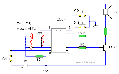
All sounds in this circuit are generated by HT2884. There are 8 different sound effect can be produced that are 2 lazer guns, 1 dual tone horn sound, 2 bomb sounds, 2 machine gun sounds and a rifle shot sound.

Note:
Power is a 3 Volt battery, but the IC will work with any voltage between 2.5 and 5 Volts. Switch S1 is the on / off switch. The output at pin 10 is amplified and drives a small 8 ohm loudspeaker. Pressing S3 once will generate all the sounds, one after another. S2 can be used to produce a single sound effect, next depression gives the next sound effect. Standby current is about 1 uA at 3 Volt, so battery life is very economical.

{ Read More }


Singular Cell Phone Can Be Used Battery 5 Exactly Like the Flashlight Without Screen

Japanese PHS operator Willcom shows the battery No. 5 mobile phone use

                                     Shaped like a remote control or torch


 Japanese PHS operator Willcom and Sanyo Electric has unveiled a battery of PHS mobile phone use. The phone has no screen, the body covered with digital dial key, shaped like a remote control or a flashlight, using a Sanyo eneloop 5 batteries.

Sanyo rechargeable battery technology has advanced, eneloop nickel-metal hydride batteries for its launch, significantly improved the "self-discharge" and other undesirable characteristics, one year after the electricity can still maintain a 80% claims to have up to five times more than ordinary battery working time and can be recharged 1000 times. Sanyo eneloop batteries have been launched based on a lot of electronic gadgets.

Willcoms mobile phone was cylindrical, 42 mm in diameter, length 134 mm, the upper part of the SIM card can be loaded for specific Willcom W-SIM. Use an eneloop battery can be sure that the phone five hours of talk time and 250 hours of standby time. At present mobile phone is still in prototype stage show.

3G mobile phone shipments in the Japanese market more than 98% and the remaining share was for the 2G mobile phones and
PHS are divided. Willcom continues to continue to bring new phones to market.

Using a Sanyo eneloop batteries, SIM cards can be put into the upper

At present mobile phone is still in prototype stage show
{ Read More }


Sensitive FM Transmitter circuit diagram

Sensitive FM Transmitter circuit diagram

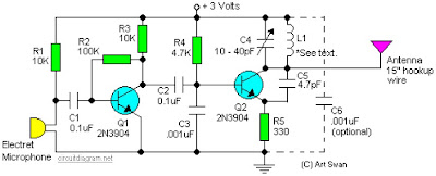
Simple and easy build of FM transmitter circuit. The circuit only require 2 transistors.


Circuit Notes:
Typically the default for the capacitors model is ceramic, preferably the npo 1% type or equivalent. However , generally almost nothing critical right here. Work with any capacitor you’ve laying arround, but DO NOT use any electrolytic or tantalum capacitors. Only in case you intend to apply this circuit outside the home you may need to use capacitores which have more temperature stability.

{ Read More }


Wednesday, June 5, 2013

Wiring Regulationsdesign Verification Electrical

 Wiring Regulations on 17th Edition Iee Wiring Regulations  Explained And Illustrated Ninth
17th Edition Iee Wiring Regulations Explained And Illustrated Ninth.


 Wiring Regulations on Source  Iee Wiring Regulations Table 4d2a
Source Iee Wiring Regulations Table 4d2a.


 Wiring Regulations on Iee Wiring Regulations  Inspection  Testing And Certification Iee
Iee Wiring Regulations Inspection Testing And Certification Iee.


 Wiring Regulations on Iee Wiring Regulations 17th Edition  Amazon Co Uk  Lighting
Iee Wiring Regulations 17th Edition Amazon Co Uk Lighting.


 Wiring Regulations on Iee Wiring Regulations Explained And Illustrated A Practical Guide To
Iee Wiring Regulations Explained And Illustrated A Practical Guide To.


 Wiring Regulations on Edition Wiring Regulations Co Uk  18th Edition Iee Wiring Regulations
Edition Wiring Regulations Co Uk 18th Edition Iee Wiring Regulations.


 Wiring Regulations on Iee Wiring Regulations  Design And Verification Of Electrical
Iee Wiring Regulations Design And Verification Of Electrical.


 Wiring Regulations on Iee Wiring Regulations  Explained And Illustrated  Sixth Edition
Iee Wiring Regulations Explained And Illustrated Sixth Edition.


 Wiring Regulations on 17th Edition Wiring Regulations Iee Bs7671 2011  Buy Online Or Call
17th Edition Wiring Regulations Iee Bs7671 2011 Buy Online Or Call.


 Wiring Regulations on 17th Edition Iee Wiring Regulations And Over One Million Other Books
17th Edition Iee Wiring Regulations And Over One Million Other Books.


{ Read More }


Rough Electrical Wiring

Electrical Wiring on Light Switch Diagram  Power Into Light     Pdf  44kb
Light Switch Diagram Power Into Light Pdf 44kb.


Electrical Wiring on Electrical Wiring Diagram Workbook Body Electrical Practice Electrical
Electrical Wiring Diagram Workbook Body Electrical Practice Electrical.


Electrical Wiring on Wiring A Switched Outlet Wiring Diagram   Electrical Online
Wiring A Switched Outlet Wiring Diagram Electrical Online.


Electrical Wiring on Rough In Electrical Wiring Af Jpg
Rough In Electrical Wiring Af Jpg.


Electrical Wiring on Electrical Wiring In The Home  Existing Nutone 665rsp Wiring
Electrical Wiring In The Home Existing Nutone 665rsp Wiring.


Electrical Wiring on 1997 Honda Civic Electrical Wiring Diagram   Circuit Schematic
1997 Honda Civic Electrical Wiring Diagram Circuit Schematic.


Electrical Wiring on Electrical Wiring Diagram
Electrical Wiring Diagram.


Electrical Wiring on Electrical Wire
Electrical Wire.


Electrical Wiring on Royalty Free Stock Photography  Electrical Wires  Image  8885437
Royalty Free Stock Photography Electrical Wires Image 8885437.


Electrical Wiring on Jch Wire   Cable   Product Catalog
Jch Wire Cable Product Catalog.


{ Read More }


Telephone Rj45 Cat5e Wiring Codes

Rj45 Wiring Diagram on Terminating Wall Plates   Structured Home Wiring
Terminating Wall Plates Structured Home Wiring.


Rj45 Wiring Diagram on Rj61 Wiring Color Code And Pinout Diagram     Circuit Diagram Wiring
Rj61 Wiring Color Code And Pinout Diagram Circuit Diagram Wiring.


Rj45 Wiring Diagram on Curt S Cat5 Wiring Diagram
Curt S Cat5 Wiring Diagram.


Rj45 Wiring Diagram on What You Should Know About Telephone And Rj45 Cat5e Wiring Codes
What You Should Know About Telephone And Rj45 Cat5e Wiring Codes.


Rj45 Wiring Diagram on Peak Electronic Design Limited   Ethernet Wiring Diagrams   Patch
Peak Electronic Design Limited Ethernet Wiring Diagrams Patch.


Rj45 Wiring Diagram on Tia Eia 568a   568b Standards For Cat5e Cable
Tia Eia 568a 568b Standards For Cat5e Cable.


Rj45 Wiring Diagram on And Solutions  Utp   Stp   Rj45 Wiring Diagram 568a   568b Standard
And Solutions Utp Stp Rj45 Wiring Diagram 568a 568b Standard.


Rj45 Wiring Diagram on Cat6 Wiring Question   Macrumors Forums
Cat6 Wiring Question Macrumors Forums.


Rj45 Wiring Diagram on Wiring   Cabling Companies In Lantana     Fiber Optics  Cat5  Cat 6
Wiring Cabling Companies In Lantana Fiber Optics Cat5 Cat 6.


Rj45 Wiring Diagram on Qvlweb  Ethernet Wiring And Loop Back
Qvlweb Ethernet Wiring And Loop Back.


{ Read More }


IconIconIconFollow Me on Pinterest