This quad final amplifier is actually intended to be used in a car, but it can naturally also be used for a variety of other medium-power applications. The TDA7375A can be successfully used in all situations in which a reasonable amount of audio power is desired and only a relatively low supply voltage is available. This IC is the successor to the TDA7374B, which forms the heart of the active loudspeaker system described earlier this year. Such a quad IC amplifier is naturally an excellent choice for this application, especially since the individual amplifiers can be connected in pairs in the bridge configuration, which allows them to provide approximately four times as much power.

In addition, all inputs have RC networks (R1/C1, etc.) to block possible RF interference. The function of R6 is to separate the grounds of the input and output stages, in order to avoid possible ground loops that might arise with the use of multiple modules. A 5-W type is used for this resistor, in order to prevent it from going up in smoke if the ground connection of the power supply comes loose. C10 decouples the internal voltage divider, which biases the internal amplifier stages to half of the supply voltage. RC network R5/C9 provides a delayed, plop-free switch-on.
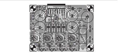

C15 and C16 are local bypass capacitors for the supply voltage. The power supply ripple rejection of the TDA7375A is approximately 50 dB. If you want to use only a transformer, bridge rectifier and smoothing capacitor for the power supply, the minimum requirement is a transformer rated at 12 V / 30 VA in combination with a 10,000-µF electrolytic capacitor (remember that the maximum allowable supply voltage is 18 V). One of the few drawbacks of this quad amplifier is that two of the channels are inverted with respect to the other two. For this reason, the polarity of each loudspeaker terminal is marked on the circuit board layout (e.g., +LS1 and –LS4) to indicate which terminal of the loudspeaker should be connected where.
Radial electrolytic capacitors rated at 3300µF/16V and having a diameter of only 12 mm are used for the output capacitors, which allows the circuit board to remain relatively compact. Our preferred type of electrolytic capacitor is a member of the Rubycon ZL series, which can handle no less than 3.4 A of ripple current. The maximum current consumption of the circuit with all four channels driven to the clipping level (with 4-Ω loads) is approximately 2.1 A. The TDA7375A can also be used with 2-Ω loads. However, in this case the internal temperature rises considerably, since the Multiwatt 15V package has a rather large thermal impedance of 1.8 ºC/W.
In the interest of the service life of the IC, it is thus a good idea to use a somewhat larger heat sink. A 4 A/T fuse has been selected in consideration of possible 2-Ω operation. If you limit the load to 4 Ω, the fuse value can be reduced to 2 A/T. The output terminals of the amplifiers can be found on the circuit board next to the associated electrolytic capacitors. The related ground connections for LS1 and LS2 are located next to the LS1 and LS2 terminals, but the ground connections for LS3 and LS4 are located on the left, next to the IC, since this gives the best current paths on the circuit board and the least distortion. Vertical car connectors (spade terminals) are used for the power supply connections.
Resistors:
R1-R4 = 100Ω
R5 = 10kΩ
R6 = 0Ω1, 5W
P1-P4 = 10 k preset
Capacitors:
C1,C3,C5,C7 = 15nF
C2,C4,C6,C8 = 220nF
C9 = 10µF 63V radial
C10 = 47µF 25V radial
C11-C14 = 3300µF 16V
C15 = 100nF
C16 = 1000µF 25V radial, max. diameter 13mm
Semiconductors:
IC1 = TDA7375A (ST)
Miscellaneous:
F1 = fuse, 4A/T (time lag), with PCB mount holder 2 fast-on (spade) terminal, male, vertical, solder type (2-pin version)
Measurement results
Supply voltage = 14.4 V
Quiescent current = 100 mA
Pmax. (0.1% THD) = 4 × 5.3 W/ 4Ω
Input sensitivity = (5.2 W/4 Ω) 0.5 V
THD+N (B = 80 kHz, 1 kHz 1W/4 Ω) = < 0.04 % Bandwidth = 28 Hz to 55 kHz
100W Quad Car Amplifier circuits.
{ Read More }
In addition, all inputs have RC networks (R1/C1, etc.) to block possible RF interference. The function of R6 is to separate the grounds of the input and output stages, in order to avoid possible ground loops that might arise with the use of multiple modules. A 5-W type is used for this resistor, in order to prevent it from going up in smoke if the ground connection of the power supply comes loose. C10 decouples the internal voltage divider, which biases the internal amplifier stages to half of the supply voltage. RC network R5/C9 provides a delayed, plop-free switch-on.
C15 and C16 are local bypass capacitors for the supply voltage. The power supply ripple rejection of the TDA7375A is approximately 50 dB. If you want to use only a transformer, bridge rectifier and smoothing capacitor for the power supply, the minimum requirement is a transformer rated at 12 V / 30 VA in combination with a 10,000-µF electrolytic capacitor (remember that the maximum allowable supply voltage is 18 V). One of the few drawbacks of this quad amplifier is that two of the channels are inverted with respect to the other two. For this reason, the polarity of each loudspeaker terminal is marked on the circuit board layout (e.g., +LS1 and –LS4) to indicate which terminal of the loudspeaker should be connected where.
Radial electrolytic capacitors rated at 3300µF/16V and having a diameter of only 12 mm are used for the output capacitors, which allows the circuit board to remain relatively compact. Our preferred type of electrolytic capacitor is a member of the Rubycon ZL series, which can handle no less than 3.4 A of ripple current. The maximum current consumption of the circuit with all four channels driven to the clipping level (with 4-Ω loads) is approximately 2.1 A. The TDA7375A can also be used with 2-Ω loads. However, in this case the internal temperature rises considerably, since the Multiwatt 15V package has a rather large thermal impedance of 1.8 ºC/W.
In the interest of the service life of the IC, it is thus a good idea to use a somewhat larger heat sink. A 4 A/T fuse has been selected in consideration of possible 2-Ω operation. If you limit the load to 4 Ω, the fuse value can be reduced to 2 A/T. The output terminals of the amplifiers can be found on the circuit board next to the associated electrolytic capacitors. The related ground connections for LS1 and LS2 are located next to the LS1 and LS2 terminals, but the ground connections for LS3 and LS4 are located on the left, next to the IC, since this gives the best current paths on the circuit board and the least distortion. Vertical car connectors (spade terminals) are used for the power supply connections.
Resistors:
R1-R4 = 100Ω
R5 = 10kΩ
R6 = 0Ω1, 5W
P1-P4 = 10 k preset
Capacitors:
C1,C3,C5,C7 = 15nF
C2,C4,C6,C8 = 220nF
C9 = 10µF 63V radial
C10 = 47µF 25V radial
C11-C14 = 3300µF 16V
C15 = 100nF
C16 = 1000µF 25V radial, max. diameter 13mm
Semiconductors:
IC1 = TDA7375A (ST)
Miscellaneous:
F1 = fuse, 4A/T (time lag), with PCB mount holder 2 fast-on (spade) terminal, male, vertical, solder type (2-pin version)
Measurement results
Supply voltage = 14.4 V
Quiescent current = 100 mA
Pmax. (0.1% THD) = 4 × 5.3 W/ 4Ω
Input sensitivity = (5.2 W/4 Ω) 0.5 V
THD+N (B = 80 kHz, 1 kHz 1W/4 Ω) = < 0.04 % Bandwidth = 28 Hz to 55 kHz
100W Quad Car Amplifier circuits.


 This design offers a way to trace resistance in the milliohm range, right to a short between bridged traces beneath a solder mask. A1 is configured as a multivibrator. R1 and C1 determine the frequency of oscillation and Q1 and Q2 boost the output. Assuming a virtual ground at the output of A2, free-run frequency is about 1kHz. Q1 and Q2 deliver a +/-10v squarewave to R4, dumping a +/-100mA through a short circuit placed across the probe tips.


