Showing posts with label light. Show all posts

Friday, July 12, 2013

Build LED Light Pen Schematic

Physicians and repair engineers often use small light pens for visual examination purposes. Rugged and expensive as these pens may be, their weak point is the bulb, which is a ‘serviceable’ part. In practice, that nearly always equates to ‘expensive’ and / or ‘impossible to find’ when you need one.

LEDs have a much longer life than bulbs and the latest ultra bright white ones also offer higher energy-to-light conversion efficiency. On the down side, LEDs require a small electronic helper circuit called ‘constant-current source’ to get the most out of them.
 
LED Light Pen Circuit Diagram
LED-Light-Pen-Circuit-Diagram

Here, T1 and R1 switch on the LED. R2 acts as a current sensor with T2 shunting off (most of) T1’s base bias current when the voltage developed across R2 exceeds about 0.65 V. The constant current through the white LED is calculated from

R2 = 0.65 / ILED
With some skill the complete circuit can be built such that its size is equal to an AA battery. The four button cells take the place of the other AA battery that used to be inside the light pen. Link


Author: Myo Min – Copyright: Elektor
{ Read More }


Thursday, July 11, 2013

UV Torch Light

UV (ultra-violet) LEDs can produce eye-catching effects when their light is allowed to interfere with certain colours, particularly with reflected light under near-dark conditions. Also try shining some UV light on a diamond.

Circuit diagram :
UV Torch Light-Circuit Diagram
 UV Torch Light Circuit Diagram

Most UV LEDs require about 3.6 V (the ‘blue’ diode voltage) to light. Here, a MAX761 step-up switching IC is used to provide constant current to bias the UV diode. The IC employs PWM in high-cur-rent mode and automatically changes to PFM mode in low or medium power mode to save (battery) power. To allow it to be used with two AA cells, the MAX761 is configured in bootstrapped mode with voltage-adjustable feedback. Up to four cells may be used to power the circuit but they may add more weight than you would like for a torchlight. 

To prolong the switch life, R1 is connected to the IC’s SHDN (shutdown) pin. Less than 50 nA will be measured in shutdown mode. Electrolytic capacitor C1 is used to decouple the circuit supply voltage. With-out it, ripple and noise may cause instability. The one inductor in the circuit, L1, may have any value between about 10 and 50 µH. It stores current in its magnetic field while the MOSFET inside the MAX761 is switched. A toroid inductor is preferred in this position as it will guarantee low stray radiation. D1 has to be a relatively fast diode so don’t be tempted to use an 1N400x because it has a too slow recovery time.
The circuit efficiency was measured at about 70%. R2, the resistor on the feed-back pin of the MAX761 effectively determines the amount of constant current, I, sent through the UV LEDs, as follows: R2 = 1.5 / I
where I will be between 2 mA and 35 mA. 

Zener diode D4 clamps the output voltage when the load is disconnected, which may happen when one of the UV LEDs breaks down. Without a load, the MAX761 will switch L1 right up to the boost voltage and so destroy itself.


Streampowers
{ Read More }


Simple Automatic Street Light

Needs no manual operation for switching ON and OFF. When there is need of light. It detects itself weather there is need for light or not. When darkness rises to a certain value then automatically street light is switched ON and when there is other source of light i.e. day time, the street light gets OFF. The sensitiveness of the street light can also be adjusted. In our project we have used four L.E.D for indication of bulb but for high power switching one can connect Relay (electromagnetic switch) at the output of pin 3 of I.C 555. Then it will be possible to turn ON/OFF any electrical appliances connected all the way through relay.

Principle :
This circuit uses a popular timer I.C 555. I.C 555 is connected as comparator with pin-6 connected with positive rail, the output goes high(1) when the trigger pin 2 is at lower then 1/3rd level of the supply voltage. Conversely the output goes low (0) when it is above 1/3rd level. So small change in the voltage of pin-2 is enough to change the level of output (pin-3) from 1 to 0 and 0 to 1. The output has only two states high and low and can not remain in any intermediate stage. It is powered by a 6V battery for portable use. The circuit is economic in power consumption. Pin 4, 6 and 8 is connected to the positive supply and pin 1 is grounded. To detect the present of an object we have used LDR and a source of light. LDR is a special type of resistance whose value depends on the brightness of the light which is falling on it. It has resistance of about 1 mega ohm when in total darkness, but a resistance of only about 5k ohms when brightness illuminated. It responds to a large part of light spectrum. We have made a potential divider circuit with LDR and 100K variable resistance connected in series. We know that voltage is directly proportional to conductance so more voltage we will get from this divider when LDR is getting light and low voltage in darkness. This divided voltage is given to pin 2 of IC 555. Variable resistance is so adjusted that it crosses potential of 1/3rd in brightness and fall below 1/3rd in darkness.

Sensitiveness can be adjusted by this variable resistance. As soon as LDR gets dark the voltage of pin 2 drops1/3rd of the supply voltage and pin 3 gets high and LED or buzzer which is connected to the output gets activated.


Component used
9v Battery with strip
Switch
L.D.R (Light Depending Resistance)
I.C NE555 with Base
L.E.D (Light Emitting Diode) 3 to 6 pieces.
Variable Resistance of 47 Kilo ohms
P.C.B (Printed Circuit Board of 555 or Vero board.

COMPONENTS :
a) Battery: For 9v power supply we can use 6pcs dry cell or 6F22 9v single piece battery.
b)Switch:Any general purpose switch can be used. Switch is used as circuit breaker.
c) L.D.R: (Light Depending Resistance)
it is a special type of resistance whose value depends on the brightness of light which is falling on it. It has resistance of about 1mega ohm when in total darkness, but a resistance of only about 5k ohms when brightness illuminated. It responds to a large part of light spectrum.
d) L.E.D:

A diode is a component that only allows electricity to flow one way. It can be thought as a sort of one way street for electrons. Because of this characteristic, diode are used to transform or rectify AC voltage into a DC voltage. Diodes have two connections, an anode and a cathode. The cathode is the end on the schematic with the point of the triangle pointing towards a line. In other words, the triangle points toward

that cathode. The anode is, of course, the opposite end. Current flows from the anode to the cathode. Light emitting diodes, or LEDs, differ from regular diodes in that when a voltage is applied, they emit light. This light can be red (most common), green, yellow, orange, blue (not very common), or infa red. LEDs are used as indicators, transmitters, etc. Most likely, a LED will never burn out like a regular lamp will and requires many times less current. Because LEDs act like regular diodes

and will form a short if connected between + and -, a current limiting resistor is used to prevent that very thing. LEDs may or may not be drawn with the circle surrounding them.

e) Variable resistance:(Potentiometer)
Resistors are one of the most common electronic components. A resistor is a device that limits, or resists current. The current limiting ability or resistance is measured in ohms, represented by the Greek symbol Omega. Variable resistors (also called potentiometers or just “pots”) are resistors that have a variable resistance. You adjust the resistance by turning a shaft. This shaft moves a wiper across the actual resistor element. By changing the amounts of resistor between the wiper connection and the connection (s) to the resistor element, you can change the resistance. You will often see the resistance of resistors written with K (kilohms) after the number value. This means that there are that many thousands of ohms. For example, 1K is 1000 ohm,2K is 2000 ohm, 3.3K is 3300 ohm, etc. You may also see the suffix M (mega ohms). This simply means million. Resistors are also rated by their power handling capability. This is the amount of heat the resistor can take before it is destroyed. The power capability is measured in W (watts) Common wattages for variable

resistors are 1/8W, 1/4W, 1/2W and 1W. Anything of a higher wattage is referred to as a rheostat
f) PCB (Printed Circuit Board)

with the help of P.C.B it is easy to assemble circuit with neat and clean end products. P.C.B is made of Bakelite with surface pasted with copper track-layout. For each components leg, hole is made.
Connection pin is passed through the hole and is soldered.
WORKING:
When light falls on the LDR then its resistance decreases which results in increase of the voltage at pin 2 of the IC 555. IC 555 has got comparator inbuilt, which compares between the input voltage from pin2 and 1/3rd of the power supply voltage. When input falls below 1/3rd then output is set high otherwise it is set low. Since in brightness, input voltage rises so we obtain no positive voltage at output of pin 3 to drive relay or LED, besides in poor light condition we get output to energize.

Precautions:
a) LDR used should be sensitive.
Before using in the circuit it should be tested with multimeter.
b) I.C should not be heated too much while soldering, can destroy the I.C. For safety and easy to replace, use of I.C base is suggested. While placing the I.C pin no 1 should be made sure at right hole.
c) Opposite polarity of battery can destroy I.C so please check the polarity before switching ON the circuit. One should use diode in series with switch for safety since diode allows flowing current in one direction only.
d) L.E.D glows in forward bias only so incorrect polarity of L.E.D will not glow. Out put voltage of our project is 7.3 volt therefore 4 LED in series can be easily used with out resistance.
e) Each component should be soldered neat and clean. We should check for any dry soldered.
f) LDR should be so adjusted that it should not get light from streetlight itself.
{ Read More }


Saturday, July 6, 2013

LIGHT ALARMS


LIGHT ALARM - 1
This circuit operates when lightweight|the sunshine} Dependent Resistor receives light. When no lightweight falls on the LDR, its resistance is high and also the transistor driving the speaker isnt turned on. When lightweight falls on the LDR its resistance decreases and also the collector of the second transistor falls. This turns off the primary transistor slightly via the second 100n and also the initial 100n puts a further spike into the bottom of the second transistor. This continues till the second transistor is turned on as onerous because it will go. the primary 100n is currently nearly charged and it cannot keep the second transistor turned on. The second transistor starts to turn off and each transistors swap conditions to provide the second half of the cycle.

LIGHT ALARM - 2


This circuit is comparable to lightweight Alarm -1 however produces a louder output as a result of the speaker being connected directly to the circuit. The circuit is essentially a high-gain amplifier thats turned on initially by the LDR and then the 10n keeps the circuit turning on till it will activate no more. The circuit then starts to show off and eventually turns off utterly. the present through the LDR starts the cycle once more.

LIGHT ALARM - 3 (MOVEMENT DETECTOR)

This circuit is extremely sensitive and may be placed in a very space to detect the movement of a person up to a pair of metres from the unit.


The circuit is essentially a high-gain amplifier (made of the primary 3 transistors) that is turned on by the LDR or photo Darlington transistor. The third transistor charges the 100u via a diode and this delivers turn-on voltage for the oscillator. The LDR has equal sensitivity to the photo transistor during this circuit.
http://streampowers.blogspot.com/2012/07/light-alarms.html 
{ Read More }


Friday, July 5, 2013

SP LED light weight Box

For beginners, its their 1st project that offers them a lift. And so as to induce that, its continuously necessary to create positive that the project that you just choose is basically helpful. One such project is that the RGB light-weight fader. this is often quite straightforward and may be done simply by a beginner. scan on to understand a lot of concerning this.


 Concerning twenty LEDs are needed here. begin by wiring all the LEDs and connecting it to a breadboard. this is often quite a tedious method and takes quite plenty of your time.

 ensuing step is to create the ability board. Quite plenty needs to be done to drive all the LEDs employing a single PWM channel. therefore to atone for this, a multiplexer IC is employed. a couple of voltage conversions is also needed in such a case.


 As mentioned earlier, one PWM is employed to regulate 3 totally different channels. The MSP430 is employed to modify between the various channels. this offers the impression that there are 3 individual channels. There is also some problems with the glint, however this might not be a show stopper downside.

 The supply code for running the circuit is kind of sophisticated . concerning twelve totally different modes are gift here and switching between the assorted modes is finished employing a single push button.
 
 
http://streampowers.blogspot.com/2012/07/sp-led-light-weight-box.html 
{ Read More }


Thursday, July 4, 2013

Automatic Bicycle Light

T his  automatic  bicycle  light  makes cycling in the dark much  easier (although you still need  to pedal of course). The circuit  takes  the  ambient  light  level  into account and only turns on  the light when it becomes dark.  The light is turned off when no  cycling has taken place for over  a minute or if it becomes light  again. The biggest advantage of  this circuit is that it has no manual controls. This way you can  never ‘forget’ to turn the light  on or off. This makes it ideal for  children and those of a forgetful  disposition.

Bicycle Light Image :
Bicycle Image Proj
To detect when the bicycle is  used (in other words, when the  wheels turn), the circuit uses a  reed switch (S1), mounted on  the frame close to the wheel.  A small magnet is fixed to the  spokes (similar to that used with  most  bicycle  speedometers),  which  closes  the  reed  switch  once for every revolution of the  wheel. Whilst the wheel turns,  pulses are fed to the base of T1  via C1. This charges a small electrolytic capacitor (C2). When it is  dark enough and the LDR there-fore has a high resistance, T2  starts conducting and the lamp  is turned on. With every revolution of the wheel C2 is charged  up again. The charge in C2 ensures that T2  keeps conducting for about a minute after  the wheel stops turning. Almost any type of  light can be connected to the output of the  circuit.

Circuit diagram :
Automatic Bicycle-Light-Circuit-Diagram
Automatic Bicycle Light Circuit Diagram
Part List :
Resistors
R1 = 1MΩ (SMD 0805)
R2,R4 = 100kΩ (SMD 0805)
R3,R6 = 1kΩ (SMD 0805)
R5 = LDR e.g. FW150 Conrad Electronics # 183547
Capacitors
C1 = 1µF 16V (SMD 0805)
C2 = 10µF 16V (SMD chip type)
C3 = 100nF (SMD 0805)
Semiconductors
T1 = BC807 (SMD SOT23)
T2 = STS6NF20V (SMD SO8)
Miscellaneous
S1 = reed switch (not on board) +
2-way right angle pinheader
BT1 = 3–12V (see text)

With a supply voltage of 3V the quiescent  current when the reed switch is open is just  0.14 μA. When the magnet happens to be in  a position such that S1 is closed,  the current is 3 μA. In either case  there is no problem using batteries to supply the circuit. The  supply voltage can be anywhere  from 3 to 12 V, depending on the  type of lamp that is connected. Since it is likely that the circuit  will be mounted inside a bicycle light it is important to keep  an eye on its dimensions. The  board has therefore been kept  very compact and use has been made of SMD components. Most  of them come in an 0805 pack-age.  C2 comes in a so called  chip version. The board is single sided with the top also acting as the solder side.
PCB
The print outline for the LDR (R5)  isn’t exactly the same as that of  the  outline  of  the  LDR  mentioned  in  the  component  list.  The outline is more a general one  because there is quite a variety  of different LDR packages on the  market. It is therefore possible  to use another type of LDR, if for  example the light threshold isn’t  quite right. The LDR may also be  mounted on the other side of the  board, but that depends on how  the board is mounted inside the  light. For the MOSFET there are also many alternatives available, such as the FDS6064N3 made  by   Fairchild ,  the  SI4864 DY  made by  Vishay Siliconix , the IR F74 0 4 made by IR F or the NTMS 4N01R 2G  made by ONSEMI. The reed switch also  comes in many different shapes and sizes; some of them are even waterproof and come with the wires already attached.

For the supply connection and  the connection to the lamp you  can either use PCB pins or solder the wires directly onto the  board. The soldered ends of the  pins can be shortened slightly so that they  don’t stick out from the bottom of the board.  This reduces the chance of shorts with any metal parts of the light. Do take care when you use a dynamo  to  power the circuit the alternating voltage must first be rectified! The same applies to  hub dynamos, which often also output an  alternating voltage.

Please Note. Bicycle lighting is subject to legal restrictions, traffic laws and, additionally in  some countries, type approval.
Download : 090102-1 PCB layout (.pdf), from www.elektor.com
Author : Ludwig Libertin (Austria) – Copyright : Elektor
{ Read More }


Monday, June 3, 2013

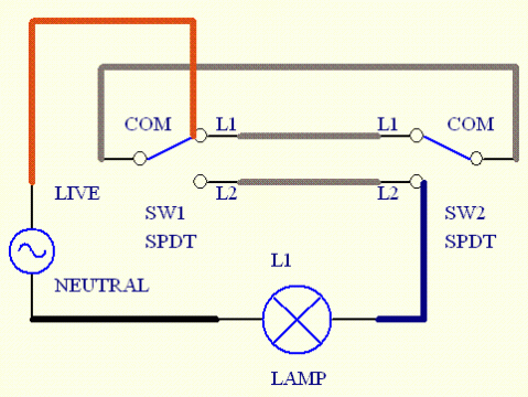
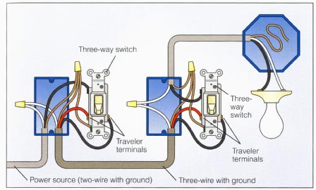
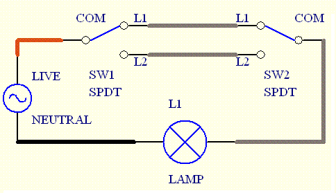
Wiringdouble Light Switch Diagramelectrical Information Blog

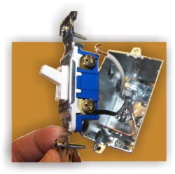
Light Switch Wiring on Wiring Diagram   I Took Some Photos Of The Wiring Mess Before I
Wiring Diagram I Took Some Photos Of The Wiring Mess Before I.


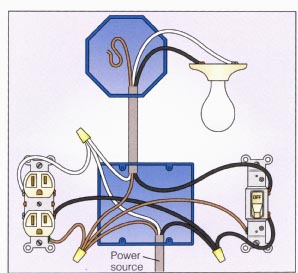
Light Switch Wiring on Review Of Switched Outlet Wiring  Power Enters At The Outlet
Review Of Switched Outlet Wiring Power Enters At The Outlet.


Light Switch Wiring on Wiring A Double Light Switch Diagram   Electrical Information Blog
Wiring A Double Light Switch Diagram Electrical Information Blog.


Light Switch Wiring on Wiring Clipsal Saturn Light Switches 2 Way Switch Wiring Diagram Jpg
Wiring Clipsal Saturn Light Switches 2 Way Switch Wiring Diagram Jpg.


Light Switch Wiring on Two Way Light Switch Wiring
Two Way Light Switch Wiring.


Light Switch Wiring on Power Light Switch Switch
Power Light Switch Switch.


Light Switch Wiring on Light Switch Wiring Diagram Uk   Reviews And Photos
Light Switch Wiring Diagram Uk Reviews And Photos.


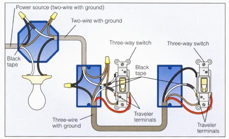
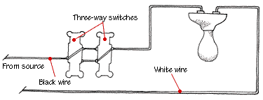
Light Switch Wiring on Three Way Light Switch Wiring
Three Way Light Switch Wiring.


Light Switch Wiring on How To Wire A Switch   Light Then Switch And Outlet
How To Wire A Switch Light Then Switch And Outlet.


Light Switch Wiring on Light Switch Wiring Headlight Switch Diagram Jpg
Light Switch Wiring Headlight Switch Diagram Jpg.


{ Read More }


Friday, May 31, 2013

Light Outlet Switch Wiring Diagram

Light Switch Wiring on Light Switch In Your Home    By Tara Gilbert Wiring A Light Switch Is
Light Switch In Your Home By Tara Gilbert Wiring A Light Switch Is.


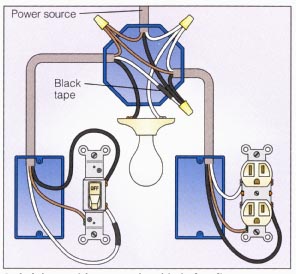
Light Switch Wiring on Light With Outlet 2 Way Switch Wiring Diagram
Light With Outlet 2 Way Switch Wiring Diagram.


Light Switch Wiring on How To Wire A Switch   Switch And Light At End Of Circuit
How To Wire A Switch Switch And Light At End Of Circuit.


Light Switch Wiring on Like The Diagram Above  Power Switch Switch Light
Like The Diagram Above Power Switch Switch Light.


Light Switch Wiring on Way As It Is The Easiest Light Switch Wiring Scenario
Way As It Is The Easiest Light Switch Wiring Scenario.


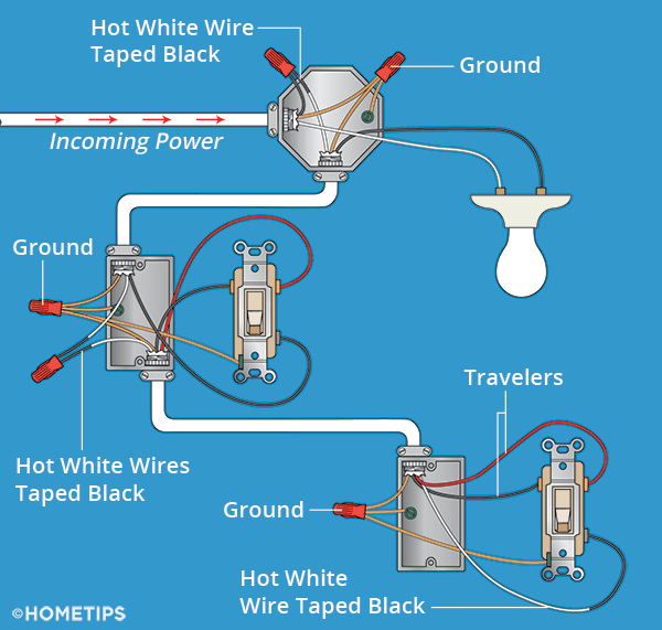
Light Switch Wiring on How To Install Light Switches   Hometips
How To Install Light Switches Hometips.


Light Switch Wiring on How To Wire A Switch   Light Then Switch At End Of Circuit
How To Wire A Switch Light Then Switch At End Of Circuit.


Light Switch Wiring on Light Switch Wiring Diagram
Light Switch Wiring Diagram.


Light Switch Wiring on Light And Outlet 2 Way Switch Wiring Diagram
Light And Outlet 2 Way Switch Wiring Diagram.


Light Switch Wiring on End Of The Corridor And You Want To Switch Off The Light The Switch
End Of The Corridor And You Want To Switch Off The Light The Switch.


{ Read More }


Friday, May 17, 2013

12V Low side and High side PWM Motor Light Controller

12V Low side and High side PWM Motor/Light Controller12V Low side PWM Motor/Light Controller
12V Low side and High side PWM Motor/Light Controller12V High side PWM Motor/Light Controller

These two schematics are variations on addition PWM circuit that I designed. The diagrams are for 12V operation alone and there are aerial ancillary (common ground) and low ancillary (common +12V) versions. The low ancillary adaptation of the ambit uses an N Channel FET, the aerial ancillary adaptation of the circuit uses a P Channel FET. N Channel accessories tend to handle added accepted than P Channel devices, they are additionally beneath expensive. The aerial ancillary adaptation of the ambit is advantageous back one ancillary of the bulk has to be grounded.

This Circuit can about-face a adequately aerial bulk of current, an IRFZ34N MOSFET can handle over 35 Amps if affiliated to a able calefaction sink. Higher ability FETs, such as the IRFZ48N or IRF1010Z can be commissioned if alike beyond currents are required. It is additionally accessible to affix assorted FETs in alongside for alike added accepted capacity. Always use thermally conductive grease amid the FET and the calefaction sink, and bethink that the calefaction bore is electrically live.

Inductive endless (motors) may crave appropriate affliction back they can accomplish ample voltage spikes that can accident the MOSFET. Replacing the 1N4002 with a fast accretion diode may advice blot the about-face voltage bang back active an anterior bulk such as a motor. If you use these circuits for abstracts with electric vehicles, be abiding to install a ambit breaker in alternation with the battery, the ambit breaker should be accessible to ability by the driver. This is abnormally important due to the actuality that back MOSFETs fail, they generally abbreviate out, abrogation the motor on at abounding speed.

Note that the pwm ascendancy has an adverse aftereffect on these two circuits, the low ancillary adaptation is on with a aerial pin 7 achievement voltage and the aerial ancillary adaptation is on with a low output.

The inductor on the aboideau ancillary of the ability MOSFET transistor can be a ferrite bean or a few turns of wire captivated about a 10 ohm, 1/4W resistor. The purpose of this allotment is to anticipate RF oscillations from occurring in the MOSFET circuitry.

{ Read More }


Saturday, April 13, 2013

Simple Light Sensor Alarm circuit with NE555

This circuit despatched out an alarm when its LDR sensor is uncovered to mild with the aid of solar or lamp. A 555 astable multivibrator was once used here which despatched sign a tone of about 1kHz upon detecting mild.The sensor when exposed by gentle fulls the circuit and makes the 555 oscillate at about 1kHz with transistor to power current.

The sensor can be shown within the circuit diagram. It has to positioned making an angle of about 30 – 45 stages to the bottom.

Sensitivity will also be modify with P1.  This makes the solar gentle to float thru it to the bottom and stops the alarm from happening as a outcome of the saved mild on the sensor.


{ Read More }


Automatic Emergency Light Circuit Diagram

This is the simple circuit of automatic emergency light. It is called dark dependent circuit. A 555 timer
IC and LDR is used for this configuration. When light fall on the LDR,
its resistance is decrease and in dark position its resistance is going
high. Using these characteristics of LDR, automatic emergency light is made.
LDR
is called Light Dependent Resistor. Its resistance is inversely
proportional to the falling light on its surface. In dark, its
resistance is approximately 7k to 10k. When light fall on its surface,
its resistance is decrease to less than 1k. In the circuit, a voltage dividerarrangement circuit is used here with LDR and 10K variable resistor.

When light fall on the surface of LDR, the resistance decrease to 1k. So the voltage of the timer pin-6 is greater than 2/3 of +Vcc. For this reason the output pin-3 goes low. The base voltage of transistor BC547 is less than 0.75 volt. The transistor is OFF state. So the light is OFF.
In dark position the LDR resistance increase is high so the voltage of the trigger pin-2 decrease to less than 1/3 of +Vcc. The output pin-3 goes high so the base voltage of the transistor BC547 is greater than 0.75 volt. The transistor is ON state. So the light is ON and it emits light.
{ Read More }


Friday, April 12, 2013

Push Bike Light

Automatic switch-on when it gets dark, 6V or 3V battery operation
This design was primarily intended to allow automatic switch-on of push-bike lights when it gets dark. Obviously, it can be used for any other purpose involving one or more lamps to be switched on and off depending of light intensity. Power can be supplied by any type of battery suitable to be fitted in your bike and having a voltage in the 3 to 6 Volts range.

The Photo resistor R1 should be fitted into the box containing the complete circuit, but a hole should be made in a convenient side of the box to allow the light hitting the sensor. Trim R2 until the desired switching threshold is reached. The setup will require some experimenting, but it should not be difficult.

Push-Bike Light Circuit Diagram

Parts:
R1_____________Photo resistor (any type)
R2______________22K 1/2W Trimmer Cermet or Carbon type
R3_______________1K 1/4W Resistor
R4_______________2K7 1/4W Resistor
R5_____________330R 1/4W Resistor (See Notes)
R6_______________1R5 1W Resistor (See Notes)
D1____________1N4148 75V 150mA Diode
Q1_____________BC547 45V 200mA NPN Transistor
Q2_____________BD438 45V 4A PNP Transistor
LP1____________Filament Lamp(s) (See Notes)
SW1_____________SPST Toggle or Slider Switch
B1______________6V or 3V Battery (See Notes)

Notes:
  • In this circuit, the maximum current and voltage delivered to the lamp(s) are limited mainly by R6 (that cant be omitted if a clean and reliable switching is expected). Therefore, the Ohms Law must be used to calculate the best voltage and current values of the bulbs.
  • For example: at 6V supply, one or more 6V bulbs having a total current drawing of 500mA can be used, but for a total current drawing of 1A, 4.5V bulbs must be chosen, as the voltage drop across R6 will become 1.5V. In this case, R6 should be a 2W type.
  • At 3V supply, R6 value can be lowered to 1 or 0.5 Ohm and the operating voltage of the bulbs should be chosen accordingly, by applying the Ohms Law.
  • Example: Supply voltage = 3V, R6 = 1R, total current drawing 600mA. Choose 2.2V bulbs as the voltage drop caused by R6 will be 0.6V.
  • At 3V supply, R5 value must be changed to 100R.
  • Stand-by current is less than 500µA, provided R2 value after trimming is set at about 5K or higher: therefore, the power switch SW1 can be omitted. If R2 value is set below 5K the stand-by current will increase substantially.
Source :   http://www.ecircuitslab.com/2011/07/push-bike-light.html
{ Read More }


LED Emergency Light Circuit Using Boost Converter

The following circuit uses a very common voltage boost converter concept for making a group of white LEDs illuminate at relatively lower power supplies. Lets learn how to make this interesting and useful little LED boost emergency light circuit.


Yet again we take the help of the evergreen work horse, the IC555 for implementing the proposed actions. The figure shows a very simple circuit configuration where the IC 555 has been rigged as an astable multivibrator.
In an astable multivibrator design the various components are wired such that the output generates trains of pulses which are self sustaining and keeps coming as long as the circuit remains powered.

In the present configuration the output of the IC which is the pin #3 generates pulses at a frequency determined by the resistors R1 and R2 and also the capacitor C2.
R2 may be typically adjusted or made variable type for enabling dimming control of the LEDs. However here the value of R2 has been fixed for acquiring optimum brightness from the LEDs.

The pulses available at pin#3 of the IC is used for ddriving the transistor T1 which in turn switches in response to the positive pulses.

The switching of the transistor pulls the supply voltage through the inductor in a pulsed mode.
As we know when alternating or pulsed voltage is applied across an inductor it tries to oppose the current and in the process kick an equivalent high voltage for compensating the applied current force.
This action of the inductor is what constitutes the boost action, where the voltage is stepped to higher levels than the actual supply voltage.
The above functioning of the inductor has been exploited in this circuit also. L1 boosts the voltage in an attempt to restrict the applied AC, this high voltage generated across the coil during the non conducting phases of the transistor is fed across a series connected LEDs for illuminating them under lower current levels. This process helps to illuminate the LEDs at relatively lower power consumption.

L1 winding is not so critical, it is a matter of little experimentation, the number of turns, wire guage, the diameter of the core, all are directly involved and affect the boost levels, therefore must be optimized carefully.
In the prototype I had used 50 turns of 22 SWG over an ordinary ferrite rod, which is normally used in small MW radio receivers.

The LEDs used by me were 1 watt, 350 mA types, howver you may use different types if you want.


Parts List

R1 = 100K
R2 = 39K,
R3 = 100 Ohms,
C1 = 680pF,
C2 = 0.01uF
L1 = see text
IC = LM555
LEDs = as per preference.

PLEASE CONNECT A 10 OHM RESISTOR IN SERIES WITH THE LED CHAIN FOR SAFEGUARDING IT FROM HIGH BOOSTED VOLTAGE.

INCREASING THE VALUE OF R2 SHOULD INCREASE THE BRIGHTNESS OF THE LEDs AND VICE VERSA.
{ Read More }


IconIconIconFollow Me on Pinterest