Showing posts with label 5. Show all posts

Sunday, July 7, 2013

4 5 Mhz Notch Filter Schematic

Component value sensitivity is extremely critical, as are temperature coefficients and matching of the components. Best performance is attained when perfectly matched components are used and when the gain of the amplifier is unity.

4.5 Mhz Notch Filter Schematic


To illustrate, the quality factor Q is very high as amplifier gain approaches 1 with all components matched (in fact, theoretically it approaches infinity) but decreases to about 12.5 with the amplifier gain at 0.98.
{ Read More }


5 Band Graphic Equaliser circuit with LA3600 and PCB

General Description
Graphic equalisers are a must in any good hi-fi systems! They enable you to shape the response of the system to the particular room, or in recordings to improve deficiencies of the equipment or the original recording. A good equalizer, used with skill can dramatically improve the quality of your listening pleasure.
This equalizer has five bands which cover all the audible frequencies, centred at 100, 320, 1,000, 3,500 and 10,000 Hz. The spacing between peak frequencies is two octaves which is quite adequate for most domestic applications. Frequency adjustment is 12dB/octave.
 
The circuit is for one channel and if you want to use it for STEREO you should build two, one for each channel of your system.
Technical Specifications – Characteristics
Working voltage: 6-15V DC
Frequency response: 20Hz-20KHz
Current: 60 ma
How it Works
This equaliser has five bands which cover all the audio frequencies, around 100, 320, 1,000, 3,500 and 10,000 Hz.
The circuit is for one channel and if you want to use it for STEREO you need two. The circuit consists of one LA3600 IC.
The circuit has been designed so that when the potentiometers are in the middle of their travel the signal is not affected at all. Turning a potentiometer in either direction will affect the corresponding frequency range accordingly. The maximum output voltage without distortion is 1 Vpp. The equaliser operates from a 12 VDC power supply which makes it suitable for use in home or car.
Construction
This work is not very difficult and if you stick to a few rules you should have no problems. The soldering iron that you use must be light and its power should not exceed the 25 Watts. The tip should be fine and must be kept clean at all times. For this purpose come very handy specially made sponges that are kept wet and from time to time you can wipe the hot tip on them to remove all the residues that tend to accumulate on it. The construction of the equaliser is very easy if you follow the diagrams and our advice carefully. The only really sensitive component are the IC. Start building the circuit by soldering the pins and the IC sockets in their places on the p.c. board. Solder then the resistors, the capacitors, making sure that the electrolytic are inserted the right way round before soldering them, and finally the potentiometers.
 
 Depending on the size and the shape of the case you are going to use for the project you can either solder the potentiometers on the p.c. board directly or use short pieces of shielded audio cable to connect them with the rest of the circuit. When you have finished soldering the components on the board check everything for possible mistakes, clean the board with a solvent to remove all traces of soldering flux and insert the IC’s in their sockets. Make sure that you align them properly and that you do not bend their pins during insertion. Make then the following connections using shielded cable for the input and output and preferably twisted twin cable for the power supply.
- The supply (6-15 VDC recommend 12volt DC) must be connected at points 1 (+) and 2 (-) of the board.
- The input is at points 5 (signal) and 4 (earth).
- The output is at points 3 (signal) and 4 (earth).
If you turn the power on, and the potentiometers of the equaliser are in their middle position there shouldn’t be any notice able difference to the music if the equaliser is inserted or not in the signal path. However turning the potentiometers should produce a noticeable effect to the reproduction.


Parts
C1 = 2.2mF 22v
C2 = 47nF
C3 = 680nF
C4 = 15nF
C5 = 220nF
C6 = 4.7nF
C7 = 68nF
C8 = 1.2nF
C9 = 22nF
C10 = 470pF
C11 = 6.8nF
C12 = 1nF
C13 = 2.2mF
C14 = 100mF 22v
C15 = 100mF 22v
R1 = 4.7k
R2 = 10k
R3, 4, 5, 6, 7 = 100k Potentiometers
IC = LA3600 link
 
{ Read More }


Wednesday, June 12, 2013

Singular Cell Phone Can Be Used Battery 5 Exactly Like the Flashlight Without Screen

Japanese PHS operator Willcom shows the battery No. 5 mobile phone use

                                     Shaped like a remote control or torch


 Japanese PHS operator Willcom and Sanyo Electric has unveiled a battery of PHS mobile phone use. The phone has no screen, the body covered with digital dial key, shaped like a remote control or a flashlight, using a Sanyo eneloop 5 batteries.

Sanyo rechargeable battery technology has advanced, eneloop nickel-metal hydride batteries for its launch, significantly improved the "self-discharge" and other undesirable characteristics, one year after the electricity can still maintain a 80% claims to have up to five times more than ordinary battery working time and can be recharged 1000 times. Sanyo eneloop batteries have been launched based on a lot of electronic gadgets.

Willcoms mobile phone was cylindrical, 42 mm in diameter, length 134 mm, the upper part of the SIM card can be loaded for specific Willcom W-SIM. Use an eneloop battery can be sure that the phone five hours of talk time and 250 hours of standby time. At present mobile phone is still in prototype stage show.

3G mobile phone shipments in the Japanese market more than 98% and the remaining share was for the 2G mobile phones and
PHS are divided. Willcom continues to continue to bring new phones to market.

Using a Sanyo eneloop batteries, SIM cards can be put into the upper

At present mobile phone is still in prototype stage show
{ Read More }


Sunday, April 7, 2013

Simple 5 Band Equalizer

This circuit uses a single chip, IC BA3812L to make 5 band graphic equalizer in audio hi-fi system. BA3812L IC is a 5-point graphic equalizer that has all functions integrated on a single IC. This IC is composed of five tone control circuit and input and output buffer amplifier. BA3812L have low distortion, low noise, and wide dynamic range, and is ideal for a variety aperanti Hi-Fi stereo. He also has a wide operating voltage range (3.5V to 16V), meaning he could be adapted for use on most stereo equipment.
5 band equalizer

The five center frequencies are independently set using external capacitors, and therefore act as an output stage buffer amplifier and tone control section is a series of its own, it is possible to do fine control over the frequency bandwidth. By using two BA3812Ls, you can create a 10-point graphic equalizer. Great header and pieces can be set by external components.

The recommended power supply of 8V, but this circuit can work well for supply voltage 9V. Limit the maximum voltage is 16V.

The circuit is given in the diagram operates in around 5 frequency bands:
100Hz , 300Hz , 1kHz , 3kHz , 10kHz
{ Read More }


Monday, April 1, 2013

Making Home Theater 5 1 Surround Amplifier

5.1 Surround Amplifier
Actually, 5.1 channel amplifier consists of 6 amplifiers 1 channel mono, which has certain specifications on each canals. Has 6 channel surround sound amplifier that consists of Front Left | Center | Front Right | Rear Left (Left Surround) | Rear Right (Right Surround) | and LFE (Subwoofer).


For clarity I give a simple illustration of the layout and the circuit for these speakers.


5.1 Speaker Setup
5.1 Speaker Setup

Accoustic Field Generator

Acoustic Field Generator is generating acoustic sound with surround effects are adjustable with a standard Dolby Surround, able to produce surround sound is good enough but not too much need of funds. Technological developments as if not only focused on one area alone but on all fronts. The development of technologies that exist today one of them is in the field of audio. With more advanced audio technology today not only as mere entertainment but has become a hobby, hobby is not cheap of course. Many audio enthusiasts trying to make music sound that sounded to be very hard to make music sound as live, the addition of the amplifier, woofer or special speakers that cost is not cheap.

The sound effects are living seems to now is something that most do not have to exist in every good audio devices. This effect is basically a surround effect that can lead to sound as though coming from different directions and his voice can still be heard clearly. Currently Compo-tape tape that has been a lot of these facilities surround sound but not good enough when heard from a considerable distance because of the effects surroundnya missing. This is because the distance is too far listener and speaker, speaker layout is not quite right, or the effect of unfavorable surround.

Surround effects are nice and can be heard with a good surround system is a system that is in movie theaters and to make it not a bit prangkat needed funds. However, if satisfaction remains the number one then the fund is not a major problem. To find a middle ground between price and quality surround effects it was attempted to make the Acoustic Field Generator that can produce surround sound is good enough but not too much need of funds. Acoustic Field Generator is capable of generating acoustic sound with surround effects are adjustable with a standard Dolby Surround.

Accoustic Field Generator Construction


Basically an Acoustic Field Generator built from op-amp circuit and filters. Op-amps are usually used as a voltage amplifier in the Acoustic Field Generator is more widely used as active filters. The filter in the tool is very instrumental in creating an acoustic sound that is really clear, but in practice, almost all the filters, do not miss the precision of the signal with a specific frequency. An op-amp is good for this application is the op-amp which has a wide bandwidth, rise time, slew rate and fast setting timenya. In addition to op-amp and active filter, theres more important parts of the power supply. This is the part that is instrumental in creating excellence acoustic sound because of the bad power supply which is the only producer of noise, which will enter into a voice signal path so that should clear acoustic sound into an acoustic sound with the addition of reverberation (noise). The power supply used is the twin power supply + / - 18 volts DC. Part Acoustic Field Generators

Before we start doing this project, it helps us know in advance about the function of each speaker.

Front Channel

Channel Front is a forward channel input signal LR. LR signal is passed to an amplifier with gain = 1 so that this signal is passed without change / to filter the input signal LR. Front Left and Front Right, is a public speaker that we encountered in stereo amplifier, consisting of a woofer and tweeter. Woofers generally produce low tone sound with a frequency range ranging from 80Hz - 250Hz, while the tweeter produces a high tone with a frequency range between 15kHz - 20kHz. For projects that we will create, its good we use a good quality woofer, with a size of 10 inches and a type piezoelectric tweeter for each speaker fronts.

Front Channel 5.1 Amplifier

Center Channel

Center, the fullrange speakers, which produce sound with a frequency range between 80Hz - 10Khz. Output from the center speaker is a summation of left and right signal (left + right = center). In a movie or song Dolby Surround format, commonly used center for dialogue / vocal or speech of the actor / artist of a film and to produce a sound that moves ahead of us.

Center Channel 5.1 Amplifier


Rear Channel with Surround System

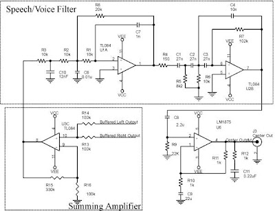
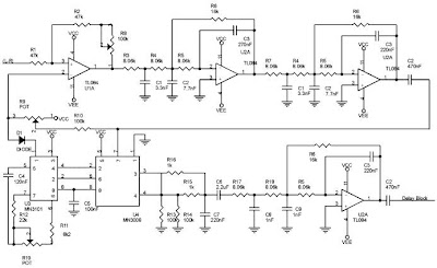
In this section is the core of this hard perangakat. These sections produce surround effects. To produce the surround effect is required special IC MN3005 / 8 and MN3101. Both these ICs will delay the incoming signal in several phases, so that the signal output from this phase will be left with a signal phase of the signal lain.Pada this section L and R are deducted (LR) and then passed in the buffer, filter LPF, delay line, filter LPF (7KHz) and the last is a splitter between the signals R and L. Circuit which causes the surround effect is 75KHz LPF circuit that produces its output fed to the Right Rear 75KHz LPF amplifier input while it diparalel with the Left Rear amplifier input so as to produce two signals L and R which is basically a LR signal a phase lag with the original signal phase.

Rear Left and Rear Right, also known as surround speakers. This speaker is generally a semi-midrange speaker (usually used on television or Mini Compo), commonly called satellite speakers. In a movie surround speakers are used to generate the audible sound of distant voices or sounds that move from the back of our approach. In a music surround speakers produce sound backing vocals and generally sounds like guitars, violins and trumpets sounded clear here.

Rear Channel 5.1 Amplifier

Subwoofer Channel

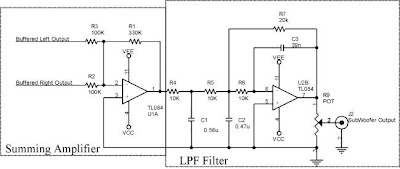
Part of this subwoofer is the summation of inputs L and R inputs to a summing amplifier. The output of the summing amplifier is passed to a class 2A LPF which will only pass signals with frequency rendah.Subwoofer, sometimes referred to as LFE (Low Frequency Effect). For these speakers using a subwoofer speaker. Speaker woofer speaker subwoofer is designed specifically to be able to respond to sound with a very low frequency, ranging from 15Hz - 120Hz. For low tone effect can be produced by either (without any harmonic frequency), then the acoustic box / box speakers are also designed specifically with a variety of methods (there are no visible speaker / inside the box, there are that use insulation / labyrinth, etc. ), so that the speaker is capable of compressing the air effectively, so that will feel the effect.

Subwoofer Channel 5.1 Amplifier


Wiring Diagram Home Theater Amplifier / 5.1 Amplifier

{ Read More }


IconIconIconFollow Me on Pinterest